You will setup four types of boundary conditions for this model
This is a simplified setup. If you use the wizard, it will create these same boundaries under separate names corresponding to each 3D component. However, the principle applied is the same.
| 1. | On the Utility menu, under BCs:, click on Create/Edit. |
| 2. | In the Boundary Conditions dialog, click BCs. |
| 3. | In the Name: field, enter Inlet. |
| 4. | For the Type: field, select Inflow. |
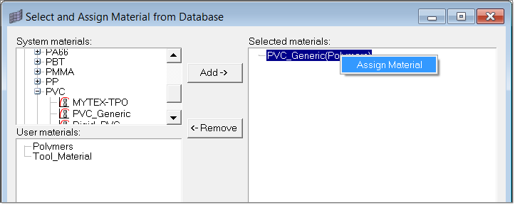
| 5. | In the Material: field, select PVC_Generic (Polymer). |
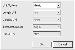
| 8. | Enter 5 mm/sec in the ZVelocity field. |
| 9. | Make sure that Temperature is selected. Enter 150 degree centigrade in the temperature field. |
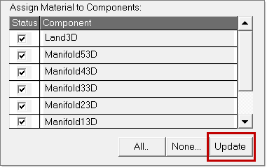
| 10. | Click Update after you have modified the velocity and temperature data. This is needed to update the BC load cards. If this step is missed, data will not be updated when you close the dialog. |
| 11. | Click on Create Faces. This will allow you to select face elements for the Inlet BC profile. |
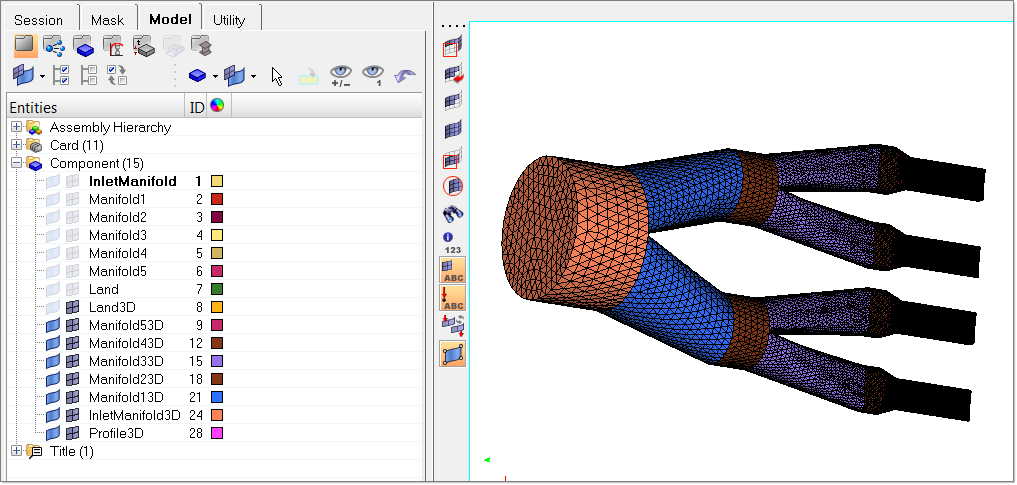
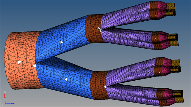
| 12. | Click one element on the inlet side of InletManifold3D and click proceed. This will create shell elements representing inflow boundary conditions. |
|
| 1. | In the Boundary Conditions dialog, click BCs again. |
| 2. | In the Name: field, enter wall. |
| 3. | For the Type: field, select SolidWall. |
| 4. | In the Material: field, select PVC_Generic (Polymer). |
| 7. | In the next panel, select Stick for Friction Model and set all three components (X, Y, and Z) of Velocity to 0. |
| 8. | Set the Heat transfer type field to Convection. |
| 9. | Enter 15 for Conv. coefficient: field. |
| 10. | Enter 40 for Conv. temperature: field. |
| 11. | Click Create Faces. This allows you to select face elements on the exit side of the profile. |
| 12. | Select a few elements on the side of all the 3D components, except Profile3D, and click proceed. This will create shell elements representing solid wall boundary conditions. This BC can be split into separate BCs for each of the manifolds, which is described in the next tutorial. |
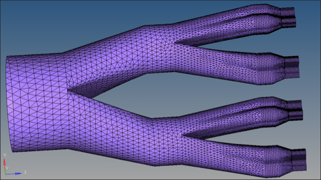
Boundary faces are captured based on break angle, hence it is important that you should select enough elements to ensure the entire side surface is captured for the SolidWall BC. In this model there are elements in sharp corners between manifolds, and you have to select them to get all BCs captured on all boundary surfaces.
|
| 1. | In the Boundary Conditions dialog, click BCs again. |
| 2. | In the Name: field, enter freesurface. |
| 3. | For the Type: field, select FreeSurface. |
| 4. | In the Material: field, select PVC_Generic (Polymer). |
| 7. | Set the Heat transfer type field to Convection. |
| 8. | Enter 15 for Conv. coefficient: field. |
| 9. | Enter 40 for Conv. temperature: field and click Update. |
| 10. | Click on Create Faces. This will allow you to select face elements on the exit side of the Profile3D. |
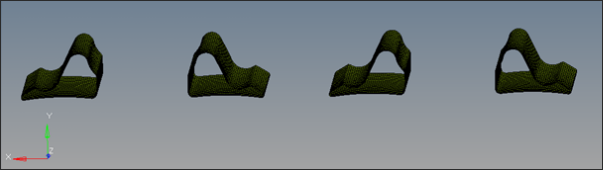
| 11. | Click on a few elements around the circumference (to overcome break angles) on the sides of all of the Profile3D blocks and click proceed. This will create shell elements representing Free Surface boundary conditions. This BC can be split into separate BCs for each of the profile blocks, which is described in the next chapter. |
Another option would be to increase the break angle.
|
| 1. | In the Boundary Conditions dialog, click BCs again. |
| 2. | In the Name: field, enter exit. |
| 3. | For the Type: field, select Outflow. |
| 4. | In the Material: field, select PVC_Generic (Polymer). |
| 7. | Check the box for Pressure and click Update. |
| 8. | Click Create Faces. This allows you to select face elements on the exit side of the profile. |
| 9. | Select a few elements on the side of all four profile blocks and click proceed. This will create shell elements representing outflow boundary conditions. |
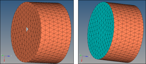
Boundary faces are captured based on break angle, hence it is important that you should select enough elements to ensure the entire side surface is captured for the Exit BC.
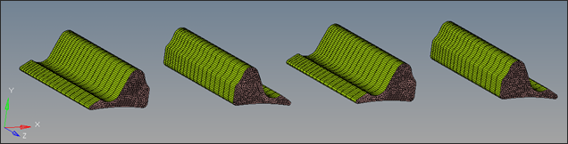
Only one of the four profile blocks is shown
| 10. | Click Close to close the dialog. |
Note:
| • | A load collector is created for each BC face which can then be card edited from the Model browser to see the BC definition. |
| • | Click on Update in the Utility menu dialog if you make any changes to the selection. |
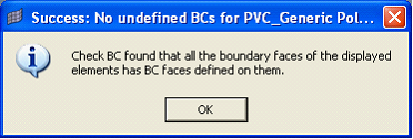
| 11. | In the Utility menu, click on Undefined. The Success window should appear. |
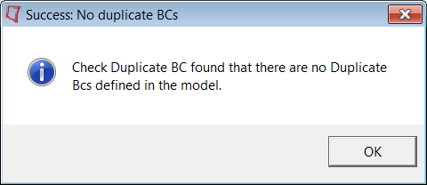
| 12. | In the Utility menu, click Duplicate. The Success window should appear. |
| 13. | If any of the above checks fail, please review the boundary faces and correct if necessary. |
|
|