In extrusion, it is common to see dies with multiple exits. In this tutorial, you will learn how to import die geometry, organize different solid entities, and generate meshes for a solid die with multiple exits. The steps to follow are:
| • | Import 3D CAD files with die geometry |
| • | Join solids using Boolean operation |
| • | Generate solver input files using the Extrusion Wizard |
The model files for this tutorial are located in the file mfs-1.zip in the subdirectory \hx\MetalExtrusion\HX_0105. See Accessing Model Files.
To work on this tutorial, it is recommended that you copy this folder to your local hard drive where you store your HyperXtrude data, for example, “C:\Users\HyperXtrude\” on a Windows machine. This will enable you to edit and modify these files without affecting the original data. In addition, it is best to keep the data on a local disk attached to the machine to improve the I/O performance of the software.
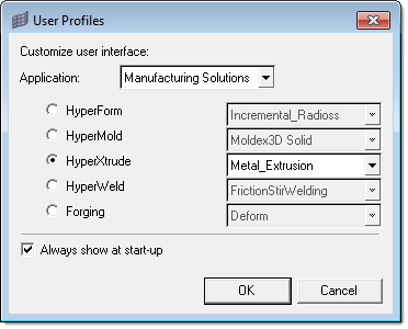
| 1. | Select Start Menu > All Programs > Altair HyperWorks > Manufacturing Solutions > HyperXtrude to launch the HyperXtrude user interface. The User Profiles dialog appears with Manufacturing Solutions as the default application. |
| 2. | Select HyperXtrude and Metal Extrusion. |
|
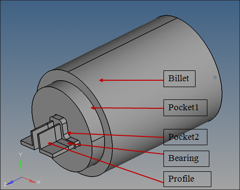
Next you will create components to store the geometry for Billet, Pocket1, Pocket2, Bearing, and Profile. To create components:
| 1. | In the Model Browser, right-click on the Component folder and select Create. |
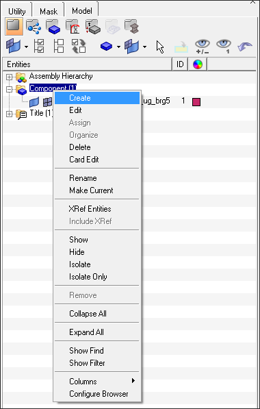
This opens the Create Component dialog.
| 2. | Enter Billet as the component name and select different color. |
| 3. | Repeat steps 1 and 2 to create the components Pocket1, Pocket2, Bearing, and Profile. |
|
| 1. | Click Collectors > Organize > Components. |
| 2. | In the panel, select the collectors subpanel and click the toggle to change the option to Solids. |
| 3. | With the Solids button active, graphically select the solid representing the Billet. |
| 4. | Click dest and select the component Billet. |
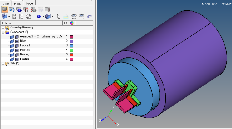
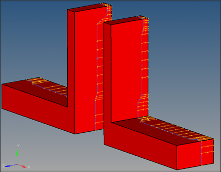
| 6. | Repeat step 3 through 5 for organizing the rest of the solids as indicated in the following figure. Use the color code in the Model Browser to identify different components. |
Note that the two Bearing solids are copied into a single component. Similarly, the two Profile solids are stored in one component.
| 7. | In the Model Browser, verify that all the solids are organized in their respective components by displaying one component at a time. Then, right-click on the empty component and select Delete. |
| Note: | To ensure that the component is empty before deleting it, right-click on Component and select Hide to hide the display of all the components. Then, select the component to delete by right-clicking on it and select Show. Empty components will have nothing to display and can be deleted. When finished deleting the empty components, right-click again on Component and select Show to display all components again. |
|
Now the solids are organized properly, but are not connected. Shared surfaces do not exist between components that are in contact. Next you will connect the individual solids and create the shared surfaces using the boolean subpanel in the Solid Edit panel.
| 1. | From the main menu, click solid edit. |
| 2. | Select the boolean subpanel and set operation type: to simple (combine all). |
| 3. | Set operation: to {A-B,B} (cut A with B). |
| 4. | With the A: Solids button activated, select the component Billet. Click the B: Solids button to activate it and select the component Pocket1. |
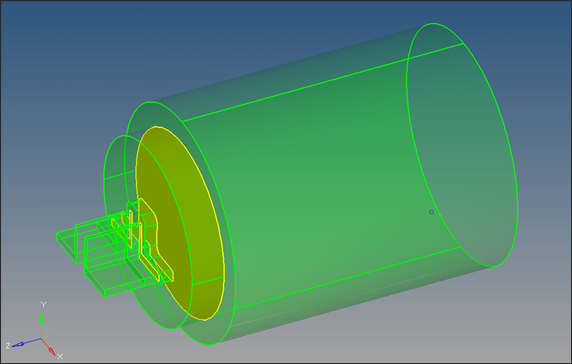
| 5. | Click calculate. This operation will join the two solids and the mating surface shared by the two solids will be shown in yellow color. |
| 6. | Repeat steps 4 and 5 to join the solids and to create shared surfaces between Pocket1 - Pocket2 and Pocket2 - Bearing. |
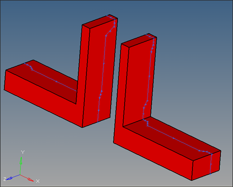
Note: Do not connect the Profile solids to the assembled geometry.
| 7. | Click return to close the panel. |
|
| 1. | Bearing curves are stored in the file HX_0105_Bearing_curves.igs. Import these lines following the procedure described in Step 1. |
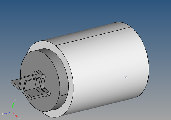
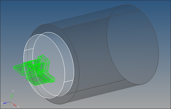
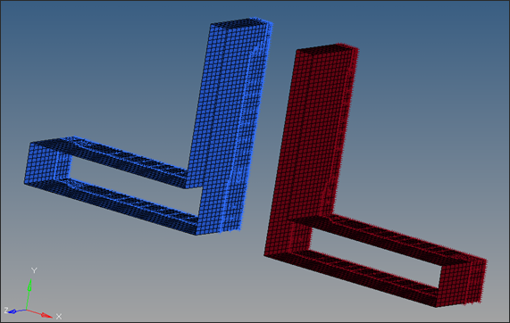
The lines are stored in components lvl1 and lvl2. The bearing profiles are defined as 3D curves. The following figure shows the display of the Bearing and the components lvl1 and lvl2.
| 2. | In the Utility Menu, click the Create Bearing Lines macro and then select Lines from Bearing Curve to to extract the bearing lengths along the die openings for each component. |
| 3. | In the selector panel that appears, click the yellow comps button and select the component lvl1. |
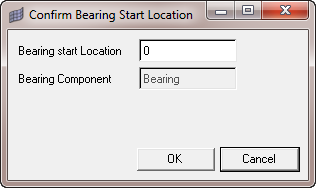
| 4. | Click select and then click proceed. This opens Confirm Bearing Start Location dialog. Verify the bearing starting location in the extrusion direction and change the default value if necessary. For this example the bearing starting location is 0. This creates the Bearing lines for lvl1. |
| 5. | Repeat steps 3 and 4 with the component lvl2. In the Model Browser, observe that the two components lvl1_lines and lvl2_lines are created. |
| 6. | Save the file by clicking on File and then Save As… and name the file HX_0105_Step5.hm. |
The model is now ready for setup.
|
| 1. | On the Utility Menu, click Extrusion Wizard. |
Depending on how you loaded the model, the Project Browser may prompt you for additional action (see HX-0004 for details).
| 2. | In the Extrusion Wizard, click the Set Model Units checkbox. |
Note: Measure dimensions of the model (ex: diameter of the billet) by pressing F4 button on the key board. Find the distance between any two nodes lying diagonally opposite to each other on the circumference of the billet. The numerical value of this distance (the diameter of the billet) gives us an idea about the unit system in which the model is created.
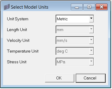
In the model, billet diameter is about 280. Hence, it is reasonable to conclude that the length unit of the model is ‘mm’. (280 inch diameter billets are practically not used in extrusion).
| 3. | Set the Unit System to Metric and set the options are shown in the figure below. Click OK. |
|
| 1. | Select Set Analysis Requirements. |
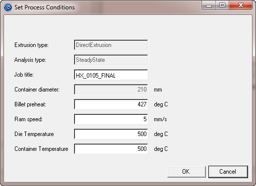
The Process Data dialog opens. Set the process data as shown below and click Next.
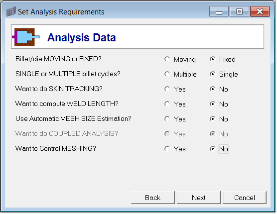
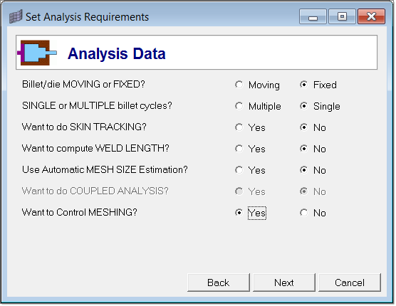
| 2. | Set the Analysis Data options are shown below and click Next. |
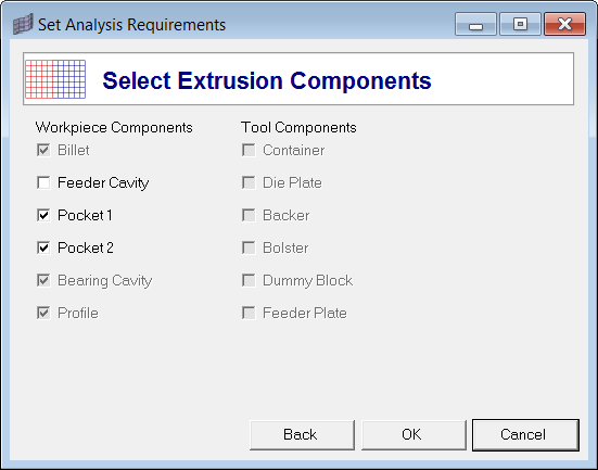
| 3. | In the Select Extrusion Components window, notice Billet, Bearing Cavity and Profile are recognized and pre-selected. Select Pocket1 and Pocket2. |
| 4. | Click OK to close this window. |
In the Extrusion Wizard, you will skip the Select Press Data step as this model does not contain the information.
|
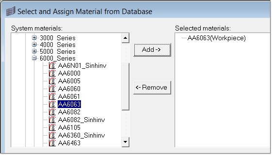
| 1. | Click Select Material Data. |
| 2. | Expand Workpiece, then expand Aluminum_Alloys and expand 6000_Series. |
| 3. | Select AA6063 and click Add-> to add the material under Selected Materials. |
You do not need to assign a material in the Extrusion Wizard. The selected material will be assigned to the workpiece automatically.
| 4. | Click Close to close the Select and Assign Material from Database window. |
|
| 1. | Click Generate Workpiece Mesh. Notice that the Extrusion Wizard already picked the components for Billet, Pocket1, Pocket2 and Bearing Cavity. |
| 2. | Input the size of the elements as shown below. |
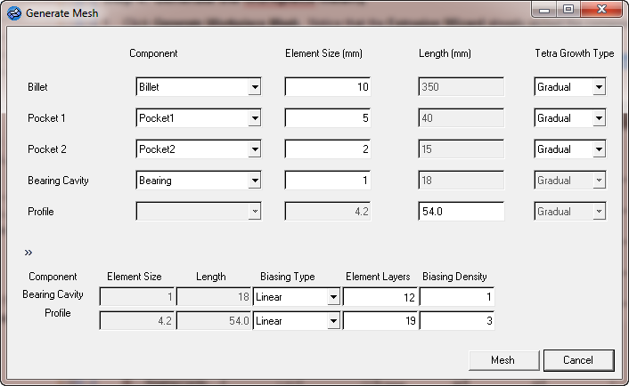
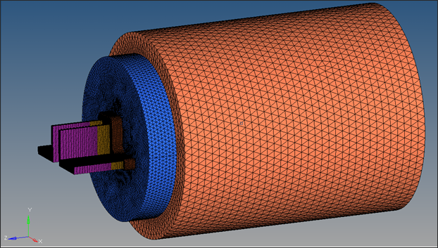
| 3. | Click Mesh. This will generate 3D mesh for Billet, Pocket1, Pocket2, Bearing and Profile. In the Model Browser, observe that the 3D mesh components Billet3D, Pocket13D, Pocket23D, Bearing3D and Profile3D are created. |
| 4. | Click on Summary in the Extrusion Wizard. Under the Element Statistics tab, click on Show Element Quality and and verify the mesh quality. If the mesh is acceptable, click OK to save and close the window. To remesh with different element sizes, edit the element sizes and click the Remesh button. In this case, the mesh quality is good, so click OK. |
|
| 1. | Click Generate Workpiece BCs and accept the default conditions. |
| 2. | Click OK. This creates BC faces and associated load cards for all the 3D collectors. |
|
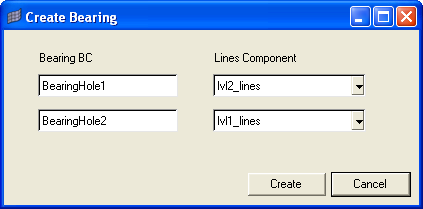
| 1. | In the Extrusion Wizard, click on Create Bearing. |
This displays the Create Bearing dialog. It shows a list of bearing boundaries and corresponding components with bearing lines for each surface.
| 2. | Verify the information and click Create to calculate bearing lengths at each node at the die orifice. |
This information is stored into the Bearing BC load component.
|
| 1. | Click Save and Export the Model and input the project file name as HX_0105_FINAL.hm. |
| 2. | Set the Model type as Three Dimensional and set the Renumber all entities field to Yes. |
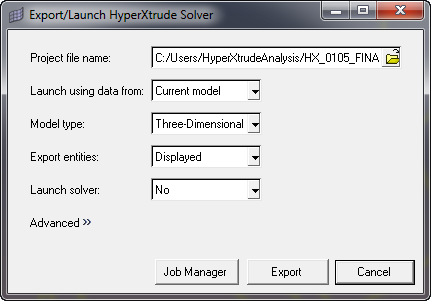
| 3. | Click Export to generate HX_0105_FINAL.grf and HX_0105_final.hx files. |
The .hx and .grf files can be passed to the HyperXtrude solver for computing the solution.
|
| 1. | Run HyperXtrude interactively or in batch mode. |
| 2. | Once the analysis is completed, post-process the results. |
|
Return to Metal Extrusion Tutorials