This subpanel creates surfaces by dragging lines or a node list along another line, called the "drag line".
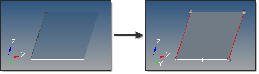
In this example, the white line is dragged along the dark gray line list one to produce a new surface.
Eight inputs are required to create a surface using this method:
| • | The lines or node list to drag. |
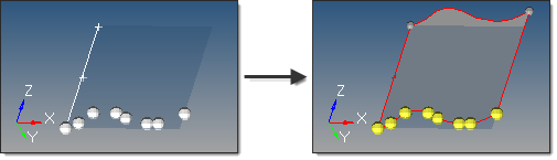
If a node list is specified, a line will first be fit through the specified nodes, then dragged:
| • | The drag line list that defines the lines that the drag will follow. This can also be a series of connected lines. |
| • | The merge input lines option applies only for lines. |
| - | If disabled, a surface is created for each input line, with shared edges connecting surfaces where relevant. |
| - | If enabled, the input lines are merged into smooth lines when possible. A surface is created for each group that forms a tangentially continuous line. |
| • | The create in method option applies only for lines. This defines the resulting surface component organization. |
| - | Selecting current component organizes the new surfaces to the current component. |
| - | Selecting lines component adds the new surfaces to the same component that the selected lines already belong to. The result is unpredictable if lines from different components become a part of the same surface. |
| • | The frame mode defines how the lines are translated and rotated during the drag. In some cases the differences are only apparent when performing relatively complex drags. The following examples for each frame mode use this starting model: |
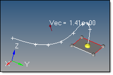
The highlighted line of the rectangular surface is dragged
along the curved line, which curves in 3 dimensions.
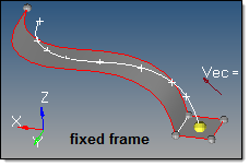
fixed frame: the lines are only translated during the drag, not rotated.
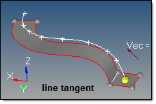
line tangent: in addition to the translation of the fixed frame option, the lines are also rotated in the same way that the tangent of the line list rotates.
Frenet frame: in addition to the translation and rotation of the line tangent option, the lines also rotate around the line list tangent axis in the same way as the curvature vector rotates.
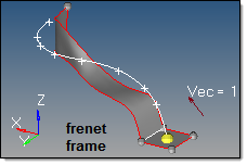
The Frenet frame option does not work well when the curvature of the line list is not smooth or includes large jumps.
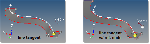
| • | The reference node and transformation plane options require the following definitions: |
| S: | start of drag line (path), which is the closest end of the drag line to the vertices of the line to be dragged. Drag + follows this direction. Drag - follows the opposite direction. |
T: tangent of the drag line at S.
R: reference node.
B: base node of the transformation plane.
N: normal vector of the transformation plane.
The reference node (R) is used to translate the drag (path) line prior to the drag, thus producing results as if the drag line actually began at the selected reference node. By default, R=S. If a different S is specified, the line list is translated by the vector defined from S to R.
The transformation plane is used to translate and rotate the input lines prior to the drag. By default, no transformation occurs (B=R and N=T). If specified, the lines are translated by the vector defined from R to B, and are rotated from N to T.
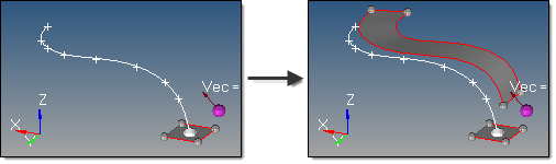
In this example, R is white and B is purple.
| • | The direction of the drag. |
Drag + is defined at the start of drag line, which is the closest end of the line to the line vertices.
Drag - is defined in the opposite direction.
How do I…
Create surfaces by dragging lines along a line
Create surfaces by dragging nodes along a line
See also
Surfaces panel


