Use the Boundary Condition Editor to create and assign boundary conditions. The Boundary Condition Editor can be accessed via the Inspect/Setup BCs macro.
The procedure to create boundary condition data involves these steps:
| 1. | Create a new BC by selecting its name, type, and color. |
| 2. | Edit the BC data and fill in all the required parameters. |
| 3. | Assign this BC to specific faces by selecting the elements, nodes, and break angle. |
The Boundary Condition Editor walks you through these steps to create and assign boundary conditions.
In the first panel of the Boundary Condition Editor (shown below), you specify a name and type for the boundary condition.
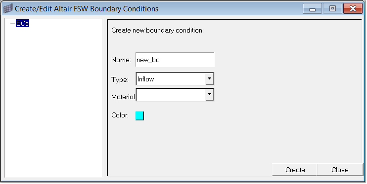
When you click Create, a load collector is created that will contain the boundary condition data and the panel is refreshed to contain fields specific to the type of boundary condition you selected, as shown in the example image below.
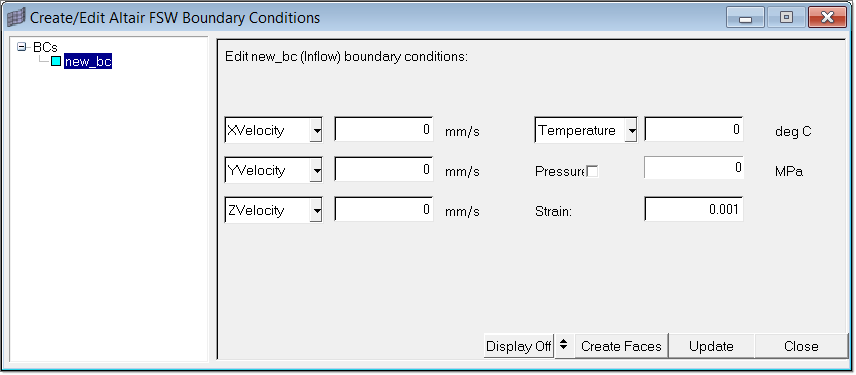
Specify data for the fields on the panel. The panel also has the following buttons:
Unmask
|
Enable the visual display of the loads.
|
Mask
|
Disable the visual display of the loads.
|
Loads
|
Create loads for the boundary condition.
|
Close
|
Close the dialog.
|
| Tip | When you specify values for temperature and velocity for an Inflow boundary condition, ensure that it is specified in the direction of the extrusion. |
After you have specified data for the boundary condition, click Loads. A dialog appears on which you can specify a break angle and vector display size. Then in the graphics area, select an element in the middle of the face on which you want to apply the loads. Click proceed to complete the load creation.
See Also:
Friction Stir Welding User's Guide


