The Auto Process feature provides an intuitive graphical interface for setting up processes such as single action draw, springback, and gravity analyses. The interface includes two tabs: Setup and Details. You can access the Auto Process macro via the Utility menu or from Tools > Auto Process.
Auto Process shortcuts are available in the following toolbar:
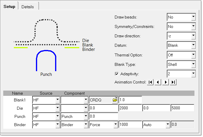
Auto Process showing a single action draw setup
Setup Tab
The first step of using the Auto Process macro is to select the type of analysis you want to perform from the Process field at the top of the dialog. The dialog is customized for the type of process you have selected.
Once an analysis type is selected, you specify the essential input parameters for the analysis in the fields that are available in the dialog. (Details about the specific fields for each analysis type are described in the How Do I topics listed below.) Each component of the process is listed in a row consisting of options you can specify. The type of option differs by component type. When you click a component in the table, the labels for the columns change to indicate what type of data you are specifying for that component.
A visual representation of the process setup is shown in the left side of the Setup tab. Note that when you have specified a HyperForm component for a process component, the visual representation changes from a dashed-line to a solid color for that component.
Once you have provided the required data, you can click the Autoposition button to automatically adjust the position of the assembly parts to achieve an efficient process. You can override some of the settings from the Autoposition feature via the fields on the dialog, such as the clearance value for a punch. Note that every tool is autopositioned with respect to the blank and a positive clearance value corresponds to movement away from the blank.
The default values for the velocities and binder force that appear under Setup can by changed by editing the process_defaults.dat file. This file also enables you to vary several other process parameters such as element formulations, number of output states, friction coefficient, etc.
The Animation Control buttons makes it possible to visually step through the process to verify that the process motion is correct. Click the arrow buttons to move forward or back through the process.
Finally, click the Apply button to save your changes and generate all the settings for your analysis.
The settings.dat file enables you to customize the environment for the Auto Process macro. For example, you can set the default process to something you commonly use.
Details Tab
From the Details tab of the Auto Process macro (shown in the image below), you can review the settings for the complete analysis, and in some cases, make modifications to the values.
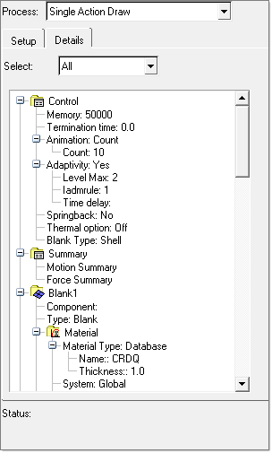
Details tab of the Auto Process macro
In the Select field, select a component whose data you want to review or select All to see all details at once. The details about various categories of data appear in a tree view in the box below the Select field. Information is provided for the following categories: control, summary, blank1, die, punch, binder, tooling, and trim. You can change the amount of displayed information by changing the corresponding parameter in the settings.dat file. See the Details Tab topic for more information about the individual settings.
Running the Analysis
After you have set up the process using the Auto Process macro, you are ready to run the analysis.
| Note: | Data created using the Auto Process macro may not have a one-to-one correspondence when viewed with the HyperForm panels. It is possible to achieve this correspondence by following these steps: |
| 1. | Delete the model in the HyperForm window. |
| 2. | Import the input deck that was created by the Auto Process macro back into HyperForm using the FE input reader. |
How Do I…
| 1. | From the toolbar, click the Double Action Draw  icon or click Tools > Auto Process. In the Process field, select Double Action Draw. icon or click Tools > Auto Process. In the Process field, select Double Action Draw. |
| 2. | Complete data in the Blank1 row. |
| a. | Select in the Source column whether the source data comes from HyperForm (HF), a geometry file (Geom file), or RADIOSS input file (STA). |
| b. | Select the relevant source in the second column based on the source type you specified in the first column – choose a HyperForm component from the drop-down, or browse for a geometry file or RADIOSS input file. |
| c. | Choose a material type in the Material column. The default material is CRDQ. If you want to select a different material, click the  button to open the Material Database, where you can view details about various materials and select a material. button to open the Material Database, where you can view details about various materials and select a material. |
| d. | Type a value for the thickness of the blank in the Thickness field. |
| e. | If the Thermal option is activated, enter a value for the Initial temperature. |
| 3. | Complete data in the Die row. |
| a. | Select in the Source column whether the source data comes from HyperForm (HF) or a geometry file (Geom file). |
| b. | Select the relevant source in the second column based on the source type you specified in the first column – choose a HyperForm component from the drop-down, or browse for a geometry file. |
| c. | If the Thermal option is activated, enter a value for the temperature. |
| 4. | Complete data in the Punch row. |
| a. | Select in the Source column whether the source data comes from HyperForm (HF) or a geometry file (Geom file). |
| b. | Select the relevant source in the second column based on the source type you specified in the first column – choose a HyperForm component from the drop-down list, or browse for a geometry file. |
| c. | In the Clearance column, type a value for the distance between the punch and the blank. This value overrides Autoposition settings. |
| d. | In the Travel 1 column, type a value for the distance the die travels toward the binder. |
| e. | In the Velocity 1 column, type a value for the velocity at which the die travels toward the binder. The suggested velocity is 2000 mm/s. |
| f. | In the Travel 2 column, type a value for the distance the die travels toward the punch. |
| g. | In the Velocity 2 column, type a value for the velocity at which the die travels toward the punch. The suggested velocity is 5000 mm/s. |
| h. | If the Thermal option is activated, enter a value for the Temperature. |
| 5. | Complete data in the Binder row. |
| a. | Select in the Source column whether the source data comes from HyperForm (HF) or a geometry file (Geom file). |
| b. | Select the relevant source in the second column based on the source type you specified in the first column – choose a HyperForm component from the drop-down, or browse for a geometry file. |
| c. | In the Travel column, type a value for the distance the die travels toward the binder. |
| d. | In the Velocity column, type a value for the velocity at which the die travels toward the binder. The suggested velocity is 2000 mm/s. |
| e. | In the Type column, select Gap or Force as the type of binder in the process. If you choose Force, type a value (in Newtons) in the Force column that appears to the right. If you choose Gap, type a value in the Gap column that appears to the right. Gap is defined as the actual physical distance between the binder and die that is maintained after the binder closure until the draw is completed, minus the blank thickness. |
| f. | If the Thermal option is activated, enter a value for the Temperature. |
| 6. | In the Draw beads field in the upper right corner of the dialog, select whether to include drawbeads in the analysis. If you select Yes, an additional row appears in the components table named Draw Beads. Click the … button to open the Drawbeads Editor. When you have finished creating and/or editing drawbeads, click Update and then Back on the Drawbeads Editor dialog. |
| 7. | In the Symmetry/Constraints field, select a plane of symmetry from the drop-down list to automatically create symmetry conditions for a symmetric model, or select No if the model is not symmetric. |
| 8. | In the Draw direction field, select the direction in which the draw is taking place. |
| 9. | In the Motion Type field, select whether the motion describes velocity or displacement. |
| 10. | Set the Thermal Option to On or Off. |
| 11. | Select the Blank Type as either Shell or Solid. |
|
| 1. | From the toolbar, click the Double Action Draw with Support  icon or click Tools > Auto Process. In the Process field, select Double Action Draw with Support. icon or click Tools > Auto Process. In the Process field, select Double Action Draw with Support. |
| 2. | Complete data in the Blank1 row. |
| a. | Select in the Source column whether the source data comes from HyperForm (HF), a geometry file (Geom file), or RADIOSS input file (STA). |
| b. | Select the relevant source in the second column based on the source type you specified in the first column – choose a HyperForm component from the drop-down, or browse for a geometry file or RADIOSS input file. |
| c. | Choose a material type in the Material column. The default material is CRDQ. If you want to select a different material, click the button to open the Material Database, where you can view details about various materials and select a material. |
| d. | Type a value for the thickness of the blank in the Thickness field. |
| e. | If the Thermal option is activated, enter a value for the Initial temperature. |
| 3. | Complete data in the Die row. |
| a. | Select in the Source column whether the source data comes from HyperForm (HF) or a geometry file (Geom file). |
| b. | Select the relevant source in the second column based on the source type you specified in the first column – choose a HyperForm component from the drop-down, or browse for a geometry file. |
| c. | If the Thermal option is activated, enter a value for the Temperature. |
| 4. | Complete data in the Support row. |
| a. | Select in the Source column whether the source data comes from HyperForm (HF) or a geometry file (Geom file). |
| b. | Select the relevant source in the second column based on the source type you specified in the first column – choose a HyperForm component from the drop-down list, or browse for a geometry file. |
| c. | In the Clearance column, type a value for the distance between the punch and the blank. This value overrides Autoposition settings. Note that the support must be initially at its original location with respect to the die before the separation occurred. |
| d. | In the To column, choose the blank or the die. |
| e. | In the Type column, select Gap or Force as the type of binder in the process. If you choose Force, type a value (in Newtons) in the Force column that appears to the right. If you choose Gap, type a value in the Gap column that appears to the right. Gap is defined as the actual physical distance between the binder and die that is maintained after the binder closure until the draw is completed, minus the blank thickness. |
| f. | If the Thermal option is activated, enter a value for the Temperature. |
| 5. | Complete data in the Punch row. |
| a. | Select in the Source column whether the source data comes from HyperForm (HF) or a geometry file (Geom file). |
| b. | Select the relevant source in the second column based on the source type you specified in the first column – choose a HyperForm component from the drop-down list, or browse for a geometry file. |
| c. | In the Clearance column, type a value for the distance between the punch and the blank. This value overrides Autoposition settings. |
| d. | In the Travel 1 column, type a value for the distance the die travels toward the binder. |
| e. | In the Velocity 1 column, type a value for the velocity at which the die travels toward the binder. The suggested velocity is 2000 mm/s. |
| f. | In the Travel 2 column, type a value for the distance the die travels toward the punch. |
| g. | In the Velocity 2 column, type a value for the velocity at which the die travels toward the punch. The suggested velocity is 5000 mm/s. |
| h. | If the Thermal option is activated, enter a value for the Temperature. |
| 6. | Complete data in the Binder row. |
| a. | Select in the Source column whether the source data comes from HyperForm (HF) or a geometry file (Geom file). |
| b. | Select the relevant source in the second column based on the source type you specified in the first column – choose a HyperForm component from the drop-down, or browse for a geometry file. |
| c. | In the Travel column, type a value for the distance the die travels toward the binder. |
| d. | In the Velocity column, type a value for the velocity at which the die travels toward the binder. The suggested velocity is 2000 mm/s. |
| e. | In the Type column, select Gap or Force as the type of binder in the process. If you choose Force, type a value (in Newtons) in the Force column that appears to the right. If you choose Gap, type a value in the Gap column that appears to the right. Gap is defined as the actual physical distance between the binder and die that is maintained after the binder closure until the draw is completed, minus the blank thickness. |
| f. | If the Thermal option is activated, enter a value for the Temperature. |
| 7. | In the Draw beads field in the upper right corner of the dialog, select whether to include drawbeads in the analysis. If you select Yes, an additional row appears in the components table named Draw Beads. Click the … button to open the Drawbeads Editor. When you have finished creating and/or editing drawbeads, click Update and then Back on the Drawbeads Editor dialog. |
| 8. | For Symmetry/Constraints, select a plane of symmetry from the drop-down list to automatically create symmetry conditions for a symmetric model, or select No if the model is not symmetric. |
| 9. | For Draw direction, select the direction in which the draw is taking place. |
| 10. | For Motion Type, select whether the motion describes velocity or displacement. |
| 11. | Set the Thermal Option to On or Off. |
| 12. | Select the Blank Type as either Shell or Solid. |
|
| 1. | From the toolbar, click the Gravity icon  or click Tools > Auto Process. In the Process field, select Gravity. or click Tools > Auto Process. In the Process field, select Gravity. |
| 2. | For Gravity Option, select either Implicit for dynamic implicit gravity or Explicit for explicit dynamic relaxation. The implicit method uses the implicit solver and generally obtains faster solution times. |
| 3. | For Number of Tools, select the number of tools that are used for the gravity model setup. |
| 4. | For Symmetry/Constraints, select a plane of symmetry from the drop-down list to automatically create symmetry conditions for a symmetric model, or select No if the model is not symmetric. |
| 5. | For Draw direction, select the direction in which the draw is taking place. |
| 6. | Select the Blank Type as either Shell or Solid. |
| 7. | Complete the data in the Blank1 row. |
| a. | Select in the Source column whether the source data comes from HyperForm (HF), a geometry file (Geom file), or RADIOSS input file (STA). |
| b. | Select the relevant source in the second column based on the source type you specified in the first column – choose a HyperForm component from the drop-down list, or browse for a geometry file or RADIOSS input file. |
| c. | Choose a material type in the Material column. The default material is CRDQ. If you want to select a different material, click the button to open the Material Database, where you can view details about various materials and select a material. |
| d. | Type a value for the thickness of the blank in the Thickness field. |
| 8. | Complete the data in the Tooling row. |
| a. | Select in the Source column whether the source data comes from HyperForm (HF) or a geometry file (Geom file). |
| b. | Select the relevant source in the second column based on the source type you specified in the first column – choose a HyperForm component from the drop-down list, or browse for a geometry file. |
| c. | Additional tooling includes a Clearance option which helps to position the corresponding tool relative to the blank. |
| Note: | The HyperForm gravity analysis assumes that the tooling is below the blank, resulting in a negative draw direction. |
|
| 1. | From the toolbar, click the Single Action Draw  icon or click Tools > Auto Process. In the Process field, select Single Action Draw. icon or click Tools > Auto Process. In the Process field, select Single Action Draw. |
| 2. | Complete data in the Blank1 row. |
| a. | Select in the Source column whether the source data comes from HyperForm (HF), a geometry file (Geom file), or RADIOSS input file (STA). |
| b. | Select the relevant source in the second column based on the source type you specified in the first column – choose a HyperForm component from the drop-down, or browse for a geometry file or LS-DYNA input file. |
| c. | Choose a material type in the Material column. The default material is CRDQ. If you want to select a different material, click the button to open the Material Database, where you can view details about various materials and select a material. |
| d. | Type a value for the thickness of the blank in the Thickness field. |
| e. | If the Thermal option is activated, enter a value for the Initial temperature. |
| 3. | Complete data in the Die row. |
| a. | Select in the Source column whether the source data comes from HyperForm (HF) or a geometry file (Geom file). |
| b. | Select the relevant source in the second column based on the source type you specified in the first column – choose a HyperForm component from the drop-down, or browse for a geometry file. |
| c. | In the Travel 1 column, type a value for the distance the die travels toward the binder. |
| d. | In the Velocity 1 column, type a value for the velocity at which the die travels toward the binder. The suggested velocity is 2000 mm/s. |
| e. | In the Travel 2 column, type a value for the distance the die travels toward the punch. |
| f. | In the Velocity 2 column, type a value for the velocity at which the die travels toward the punch. The suggested velocity is 5000 mm/s. |
| g. | If the Thermal option is activated, enter a value for the Temperature. |
| 4. | Complete data in the Punch row. |
| a. | Select in the Source column whether the source data comes from HyperForm (HF) or a geometry file (Geom file). |
| b. | Select the relevant source in the second column based on the source type you specified in the first column – choose a HyperForm component from the drop-down, or browse for a geometry file. |
| c. | In the Clearance column, type a value for the distance between the punch and the blank. This value will override Autoposition settings. |
| d. | If the Thermal option is activated, enter a value for the Temperature. |
| 5. | Complete data in the Binder row. |
| a. | Select in the Source column whether the source data comes from HyperForm (HF) or a geometry file (Geom file). |
| b. | Select the relevant source in the second column based on the source type you specified in the first column – choose a HyperForm component from the drop-down, or browse for a geometry file. |
| c. | In the Type column, select Gap or Force as the type of binder in the process. If you choose Force, type a value (in Newtons) in the Force column that appears to the right. If you choose Gap, type a value in the Gap column that appears to the right. Gap is defined as the actual physical distance between the binder and die that is maintained after the binder closure until the draw is completed, minus the blank thickness. |
| d. | If the Thermal option is activated, enter a value for the Temperature. |
| 6. | In the Draw beads field in the upper right corner of the dialog, select whether to include drawbeads in the analysis. If you select Yes, an additional row appears in the components table named Draw Beads. In the Goto column, click the … button to open the Drawbeads Editor. When you have finished creating and/or editing drawbeads, click Update and then Back on the Drawbeads Editor dialog. |
| 7. | In the Symmetry/Constraints field, select a plane of symmetry from the drop-down list to automatically create symmetry conditions for a symmetric model, or select No if the model is not symmetric. |
| 8. | In the Draw direction field, select the direction in which the draw is taking place. |
| 9. | In the Motion Type field, select whether the motion describes velocity or displacement. |
| 10. | Set the Thermal option to On or Off. |
| 11. | Select the Blank Type as either Shell or Solid. |
|
| 1. | From the toolbar, click the Springback  icon or click Tools > Auto Process. In the Process field, select Springback. icon or click Tools > Auto Process. In the Process field, select Springback. |
| 2. | Complete data in the Blank1 row. |
| a. | Select in the Source column whether the source data comes from HyperForm (HF), or a RADIOSS input file (STA). |
| b. | Select the relevant source in the second column based on the source type you specified in the first column – choose a HyperForm component from the drop-down, or browse for a RADIOSS input file. |
| c. | Choose a material type in the Material column. The default material is CRDQ. If you want to select a different material, click the button to open the Material Database, where you can view details about various materials and select a material. |
| d. | Type a value for the thickness of the blank in the Thickness field. |
3. Select the Blank Type as either Shell or Solid.
|
| 1. | From the toolbar, click the Triple Action Draw  icon or click Tools > Auto Process. In the Process field, select Triple Action Draw. icon or click Tools > Auto Process. In the Process field, select Triple Action Draw. |
| 2. | Complete data in the Blank1 row. |
| a. | Select in the Source column whether the source data comes from HyperForm (HF), a geometry file (Geom file), or RADOSS input file (STA). |
| b. | Select the relevant source in the second column based on the source type you specified in the first column – choose a HyperForm component from the drop-down, or browse for a geometry file or RADIOSS input file. |
| c. | Choose a material type in the Material column. The default material is CRDQ. If you want to select a different material, click the button to open the Material Database, where you can view details about various materials and select a material. |
| d. | Type a value for the thickness of the blank in the Thickness field. |
| e. | If the Thermal option is activated, enter a value for the Initial temperature. |
| 3. | Complete data in the Die row. |
| a. | Select in the Source column whether the source data comes from HyperForm (HF) or a geometry file (Geom file). |
| b. | Select the relevant source in the second column based on the source type you specified in the first column – choose a HyperForm component from the drop-down, or browse for a geometry file. |
| c. | In the Clearance column, type a value for the distance between the die and the blank. This value overrides Autoposition settings. |
| d. | In the Travel 1 column, type a value for the distance the die travels toward the binder. |
| e. | In the Velocity 1 column, type a value for the velocity at which the die travels toward the binder. The suggested velocity is 2000 mm/s. |
| f. | In the Travel 2 column, type a value for the distance the die travels toward the punch. |
| g. | In the Velocity 2 column, type a value for the velocity at which the die travels toward the punch. The suggested velocity is 5000 mm/s. |
| h. | If the Thermal option is activated, enter a value for the Temperature. |
| 4. | Complete data in the Punch row. |
| a. | Select in the Source column whether the source data comes from HyperForm (HF) or a geometry file (Geom file). |
| b. | Select the relevant source in the second column based on the source type you specified in the first column – choose a HyperForm component from the drop-down, or browse for a geometry file. |
| c. | In the Clearance column, type a value for the distance between the die and the blank. This value overrides Autoposition settings. |
| d. | If the Thermal option is activated, enter a value for the Temperature. |
| 5. | Complete data in the UpperBinder row. |
| a. | Select in the Source column whether the source data comes from HyperForm (HF) or a geometry file (Geom file). |
| b. | Select the relevant source in the second column based on the source type you specified in the first column – choose a HyperForm component from the drop-down list, or browse for a geometry file. |
| c. | In the Travel column, type a value for the distance the upper binder travels toward the blank. |
| d. | In the Velocity column, type a value for the velocity at which the upper binder travels toward the blank. The suggested velocity is 2000 mm/s. |
| e. | If the Thermal option is activated, enter a value for the Temperature. |
| 6. | Complete data in the LowerBinder row. |
| a. | Select in the Source column whether the source data comes from HyperForm (HF) or a geometry file (Geom file). |
| b. | Select the relevant source in the second column based on the source type you specified in the first column – choose a HyperForm component from the drop-down list, or browse for a geometry file. |
| c. | In the Type column, select Gap or Force as the type of binder in the process. If you choose Force, type a value (in Newtons) in the Force column that appears to the right. If you choose Gap, type a value in the Gap column that appears to the right. Gap is defined as the actual physical distance between the lower binder and the upper binder that is maintained after the binder closure until the draw is completed, minus the blank thickness. |
| d. | If the Thermal option is activated, enter a value for the Temperature. |
| 7. | In the Draw beads field in the upper right corner of the dialog, select whether to include drawbeads in the analysis. If you select Yes, an additional row appears in the components table named Draw Beads. In the Goto column, click the … button to open the Drawbeads Editor. When you have finished creating and/or editing drawbeads, click Update and then Back on the Drawbeads Editor dialog. |
| 8. | In the Symmetry/Constraints field, select a plane of symmetry from the drop-down list to automatically create symmetry conditions for a symmetric model, or select No if the model is not symmetric. |
| 9. | In the Draw direction field, select the direction in which the draw is taking place. |
| 10. | In the Motion Type field, select whether the motion describes velocity or displacement. |
| 11. | Set the Thermal Option to On or Off. |
| 12. | Select the Blank Type as either Shell or Solid. |
|
| 1. | From the toolbar, click the Trimming  icon or click Tools > Auto Process. In the Process field, select Trimming. icon or click Tools > Auto Process. In the Process field, select Trimming. |
| 2. | Complete data in the Blank1 row. |
| a. | Select in the Source column whether the source data comes from HyperForm (HF), a geometry file (Geom file), or RADIOSS input file (STA). |
| b. | Select the relevant source in the second column based on the source type you specified in the first column – choose a HyperForm component from the drop-down, or browse for a geometry file or RADIOSS input file. |
| c. | Choose a material type in the Material column. The default material is CRDQ. If you want to select a different material, click the button to open the Material Database, where you can view details about various materials and select a material. |
| d. | Type a value for the thickness of the blank in the Thickness field. |
| 3. | Complete data in the Trim row. |
| a. | Select in the Source column whether the source data comes from HyperForm (HF) or a geometry file (Geom file). |
| b. | Select the relevant source in the second column based on the source type you specified in the first column – choose a HyperForm component from the drop-down list, or browse for a geometry file. |
| c. | In the Remove column, select whether material is removed from inside or outside the trim line. |
| d. | In the Tolerance column, enter a value for the tolerance. |
|
| 1. | From the toolbar, click the Crash Form  icon or click Tools > Auto Process. In the Process field, select Crash Form. icon or click Tools > Auto Process. In the Process field, select Crash Form. |
| 2. | Complete data in the Blank1 row. |
| a. | Select in the Source column whether the source data comes from HyperForm (HF), a geometry file (Geom file), or RADIOSS input file (STA). |
| b. | Select the relevant source in the second column based on the source type you specified in the first column – choose a HyperForm component from the drop-down, or browse for a geometry file or RADIOSS input file. |
| c. | Choose a material type in the Material column. The default material is CRDQ. If you want to select a different material, click the button to open the Material Database, where you can view details about various materials and select a material. |
| d. | Type a value for the thickness of the blank in the Thickness field. |
| e. | If the Thermal option is activated, enter a value for the Initial temperature. |
| 3. | Complete data in the Die row. |
| a. | Select in the Source column whether the source data comes from HyperForm (HF) or a geometry file (Geom file). |
| b. | Select the relevant source in the second column based on the source type you specified in the first column – choose a HyperForm component from the drop-down, or browse for a geometry file. |
| c. | If the Thermal option is activated, enter a value for the Temperature. |
| 4. | Complete data in the Punch row. |
| a. | Select in the Source column whether the source data comes from HyperForm (HF) or a geometry file (Geom file). |
| b. | Select the relevant source in the second column based on the source type you specified in the first column – choose a HyperForm component from the drop-down, or browse for a geometry file. |
| c. | In the Clearance column, type a value for the distance between the punch and the blank. This value will override Autoposition settings. |
| d. | In the Travel column, type a value for the distance the punch travels toward the binder. |
| e. | In the Velocity column, type a value for the velocity at which the punch travels toward the binder. The suggested velocity is 5000 mm/s. |
| f. | If the Thermal option is activated, enter a value for the Temperature. |
| 5. | In the Draw beads field in the upper right corner of the dialog, select whether to include drawbeads in the analysis. If you select Yes, an additional row appears in the components table named Draw Beads. In the Goto column, click the … button to open the Drawbeads Editor. When you have finished creating and/or editing drawbeads, click Update and then Back on the Drawbeads Editor dialog. |
| 6. | In the Symmetry/Constraints field, select a plane of symmetry from the drop-down list to automatically create symmetry conditions for a symmetric model, or select No if the model is not symmetric. |
| 7. | In the Draw direction field, select the direction in which the draw is taking place. |
| 8. | In the Motion Type field, select whether the motion describes velocity or displacement. |
| 9. | Set the Thermal Option to On or Off. |
| 10. | Select the Blank Type as either Shell or Solid. |
|
| 1. | From the toolbar, click the Flanging  icon or click Tools > Auto Process. In the Process field, select Flanging. icon or click Tools > Auto Process. In the Process field, select Flanging. |
| 2. | Complete data in the Blank1 row. |
| a. | Select in the Source column whether the source data comes from HyperForm (HF), a geometry file (Geom file), or RADIOSS input file (STA). |
| b. | Select the relevant source in the second column based on the source type you specified in the first column – choose a HyperForm component from the drop-down, or browse for a geometry file or RADIOSS input file. |
| c. | Choose a material type in the Material column. The default material is CRDQ. If you want to select a different material, click the button to open the Material Database, where you can view details about various materials and select a material. |
| d. | Type a value for the thickness of the blank in the Thickness field. |
| e. | If the Thermal option is activated, enter a value for the Initial temperature. |
| 3. | Complete data in the Die row. |
| a. | Select in the Source column whether the source data comes from HyperForm (HF) or a geometry file (Geom file). |
| b. | Select the relevant source in the second column based on the source type you specified in the first column – choose a HyperForm component from the drop-down, or browse for a geometry file. |
| c. | If the Thermal option is activated, enter a value for the Temperature. |
| 4. | Complete data in the Wiper row. |
| a. | Select in the Source column whether the source data comes from HyperForm (HF) or a geometry file (Geom file). |
| b. | Select the relevant source in the second column based on the source type you specified in the first column – choose a HyperForm component from the drop-down, or browse for a geometry file. |
| c. | In the Clearance column, type a value for the distance between the wiper and the blank. This value will override Autoposition settings. |
| d. | In the Travel 1 column, type a value for the distance the wiper travels toward the binder. |
| e. | In the Velocity 1 column, type a value for the velocity at which the wiper travels toward the binder. The suggested velocity is 2000 mm/s. |
| f. | In the Travel 2 column, type a value for the distance the wiper travels toward the punch. |
| g. | In the Velocity 2 column, type a value for the velocity at which the wiper travels toward the punch. The suggested velocity is 5000 mm/s. |
| h. | If the Thermal option is activated, enter a value for the Temperature. |
| 5. | Complete data in the Pad row. |
| a. | Select in the Source column whether the source data comes from HyperForm (HF) or a geometry file (Geom file). |
| b. | Select the relevant source in the second column based on the source type you specified in the first column – choose a HyperForm component from the drop-down, or browse for a geometry file. |
| c. | In the Travel column, type a value for the distance the pad travels toward the binder. |
| d. | In the Velocity column, type a value for the velocity at which the pad travels toward the binder. The suggested velocity is 2000 mm/s. |
| e. | In the Type column, select Gap or Force as the type of binder in the process. If you choose Force, type a value (in Newtons) in the Force column that appears to the right. If you choose Gap, type a value in the Gap column that appears to the right. Gap is defined as the actual physical distance between the binder and die that is maintained after the binder closure until the draw is completed, minus the blank thickness. |
| f. | If the Thermal option is activated, enter a value for the Temperature. |
| 6. | In the Draw beads field in the upper right corner of the dialog, select whether to include drawbeads in the analysis. If you select Yes, an additional row appears in the components table named Draw Beads. In the Goto column, click the … button to open the Drawbeads Editor. When you have finished creating and/or editing drawbeads, click Update and then Back on the Drawbeads Editor dialog. |
| 7. | In the Symmetry/Constraints field, select a plane of symmetry from the drop-down list to automatically create symmetry conditions for a symmetric model, or select No if the model is not symmetric. |
| 8. | In the Draw direction field, select the direction in which the draw is taking place. |
| 9. | In the Motion Type field, select whether the motion describes velocity or displacement. |
| 10. | Set the Thermal Option to On or Off. |
| 11. | Select the Blank Type as either Shell or Solid. |
|
| 1. | From the toolbar, click the Single Action Draw with Support  icon or click Tools > Auto Process. In the Process field, select Single Action Draw with Support. icon or click Tools > Auto Process. In the Process field, select Single Action Draw with Support. |
| 2. | Complete data in the Blank1 row. |
| a. | Select in the Source column whether the source data comes from HyperForm (HF), a geometry file (Geom file), or RADIOSS input file (STA). |
| b. | Select the relevant source in the second column based on the source type you specified in the first column – choose a HyperForm component from the drop-down, or browse for a geometry file or RADIOSS input file. |
| c. | Choose a material type in the Material column. The default material is CRDQ. If you want to select a different material, click the button to open the Material Database, where you can view details about various materials and select a material. |
| d. | Type a value for the thickness of the blank in the Thickness field. |
| e. | If the Thermal option is activated, enter a value for the Initial temperature. |
| 3. | Complete data in the Die row. |
| a. | Select in the Source column whether the source data comes from HyperForm (HF) or a geometry file (Geom file). |
| b. | Select the relevant source in the second column based on the source type you specified in the first column – choose a HyperForm component from the drop-down, or browse for a geometry file. |
| c. | In the Travel 1 column, type a value for the distance the die travels toward the binder. |
| d. | In the Velocity 1 column, type a value for the velocity at which the die travels toward the binder. The suggested velocity is 2000 mm/s. |
| e. | In the Travel 2 column, type a value for the distance the die travels toward the punch. |
| f. | In the Velocity 2 column, type a value for the velocity at which the die travels toward the punch. The suggested velocity is 5000 mm/s. |
| g. | If the Thermal option is activated, enter a value for the Temperature. |
| 4. | Complete data in the Punch row. |
| a. | Select in the Source column whether the source data comes from HyperForm (HF) or a geometry file (Geom file). |
| b. | Select the relevant source in the second column based on the source type you specified in the first column – choose a HyperForm component from the drop-down list, or browse for a geometry file. |
| c. | In the Clearance column, type a value for the distance between the punch and the blank. This value overrides Autoposition settings. |
| d. | If the Thermal option is activated, enter a value for the Temperature. |
| 5. | Complete data in the Support row. |
| a. | Select in the Source column whether the source data comes from HyperForm (HF) or a geometry file (Geom file). |
| b. | Select the relevant source in the second column based on the source type you specified in the first column – choose a HyperForm component from the drop-down list, or browse for a geometry file. |
| c. | In the Travel column, type a value for the distance the die travels toward the binder. |
| d. | In the Velocity column, type a value for the velocity at which the die travels toward the binder. The suggested velocity is 2000 mm/s. |
| e. | In the Type column, select Gap or Force as the type of binder in the process. If you choose Force, type a value (in Newtons) in the Force column that appears to the right. If you choose Gap, type a value in the Gap column that appears to the right. Gap is defined as the actual physical distance between the binder and die that is maintained after the binder closure until the draw is completed, minus the blank thickness. |
| f. | If the Thermal option is activated, enter a value for the Temperature. |
| 6. | Complete data in the Binder row. |
| a. | Select in the Source column whether the source data comes from HyperForm (HF) or a geometry file (Geom file). |
| b. | Select the relevant source in the second column based on the source type you specified in the first column – choose a HyperForm component from the drop-down, or browse for a geometry file. |
| c. | In the Type column, select Gap or Force as the type of binder in the process. If you choose Force, type a value (in Newtons) in the Force column that appears to the right. If you choose Gap, type a value in the Gap column that appears to the right. Gap is defined as the actual physical distance between the binder and die that is maintained after the binder closure until the draw is completed, minus the blank thickness. |
| d. | If the Thermal option is activated, enter a value for the Temperature. |
| 7. | In the Draw beads field in the upper right corner of the dialog, select whether to include drawbeads in the analysis. If you select Yes, an additional row appears in the components table named Draw Beads. Click the … button to open the Drawbeads Editor. When you have finished creating and/or editing drawbeads, click Update and then Back on the Drawbeads Editor dialog. |
| 8. | In the Symmetry/Constraints field, select a plane of symmetry from the drop-down list to automatically create symmetry conditions for a symmetric model, or select No if the model is not symmetric. |
| 9. | In the Draw direction field, select the direction in which the draw is taking place. |
| 10. | In the Motion Type field, select whether the motion describes velocity or displacement. |
| 11. | Set the Thermal Option to On or Off. |
| 12. | Select the Blank Type as either Shell or Solid. |
|
See also
Tools
Details Tab


