Use the Local tool to create a design within a predetermined localized region of an
existing model. The tool will automatically patch the open voids, create the voxel design
space, and create a TIE contact between the local design space and the surrounding
structure.
It is necessary to prepare the model beforehand; preparation must include
patching open holes or gaps that are larger than the desired voxel mesh size.
Using a combination of hole/gap fill and shrink wrap will get the model to the
point it’s ready for local design space creation.
It’s important to turn off the part(s) that are not applicable for the local
design space creation and/or deselect them when selecting the appropriate
part(s) for design space creation. It’s often easier to make the display
selection ready before entering the workflow.
The local design space workflow is designed to facilitate rapid model generation for
topology optimization. Typical applications may include the concept design
exploration of structural inserts or baffles within an enclosed structure.
The images below show 1) the local design space created and 2) the topology result
which is ready for design interpretation.Figure 1. Local design spaceFigure 2. Topology result
The local design space workflow will by default create the voxels at the voids only.
It will not create voxels that intersect the structure – see the image below, Voids
Only.Figure 3.
From the Design Space ribbon, click the
Local tool.
Figure 4.
Click on the guide bar to define
mesh size and TIE contact settings.
Select the location of interest where the design space will be created.
Option
Description
Local Design Space
Create a new deign space within a specified bounding box.
Select a node or location to define the center of the bounding
box.
Adjust the dimensions, position, and orientation of the box
using the manipulators and microdialogs.
All elements within the bounding box are considered
for the creation of the design space.
Symmetry
Create one or more design spaces that are in symmetry or
reflected.
Select a pre-existing design space to reflect.
Click the Symmetry selector on the
guide bar then select an existing
symmetry plane, or right-click in empty space and select
Create New to define a new
plane.
Optional: Select exclude volume entities.
Exclude volume entities define the non-design parts and/or subsystems. All
space within the exclude will be exempt from having voxels created within
it.
Components and elements are supported. Change the entity type from the
guide bar selector.
On the guide bar, click one of the following:
- Save changes and stay in the tool
- Save changes and close the tool
- Exit the tool without saving changes
After confirming your selection:
A local design space is created within the selected area.
A TIE contact is created between the design space and the structure.
Design variable cards (DTPL) are setup for topology optimization.
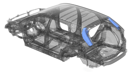 Figure 1. Local design space
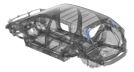 Figure 2. Topology result
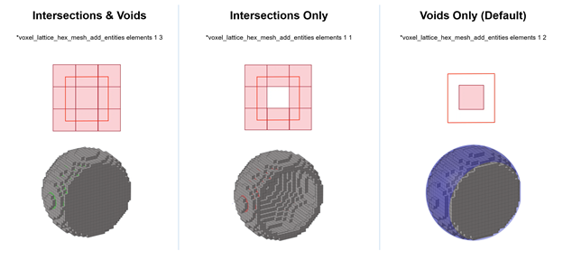 Figure 3.
 on the guide bar to define
mesh size and TIE contact settings.
on the guide bar to define
mesh size and TIE contact settings.
 - Save changes and stay in the tool
 - Save changes and close the tool
 - Exit the tool without saving changes