Before you can successfully solid mesh a model, ensure that the solids have been
partitioned so that they are either one directional or three directional
mappable.
Solid (3D) meshing can be done automatically, just like 2D shell meshing, but often
requires that complex parts be partitioned into groups of smaller, simpler,
connected solids instead of one large complex solid. In solid meshing, the ability
to be meshed is referred to as mappability.
Mappability is directional and can be likened to putting a surface mesh on one face
of the solid, then extending that mesh along a vector through the solid volume. So,
for example, a perfect cylinder is mappable in one direction, the axis between its
top and bottom faces, while a perfect cube is mappable in three, the axes between
each pair of its identical faces. However, a combustion engine's cylinder head
consisting of two cylinders of different radius joined together into a single solid
entity would need to be partitioned to divide the two cylinders. Once partitioned,
each cylinder would become mappable in one direction.
Note: Even when all partitioned
sections of the solid are mappable, this does not necessarily mean that they can
all be meshed at once. In some cases they may need to be meshed a few at a time,
or even individually in extreme cases. Mappability only ensures that the
partitioned section can be meshed.
Use the Mappable visualization mode to review solid partitioning for mappability. The
“Mappable” mode color codes the solids within the model according to whether the
solids are solid meshable. The ignored map, not mappable, 1 directional map, and 3
directional map all relate to the mappable state of the solids.
Tip: Change the color coding for the mappable state from the Options panel, Colors
subpanel.
When reading in a new model with solids, the model will be colored blue after you
activate the Mappable visualization mode, which indicates that the mappability is
currently being ignored. It is then necessary to partition the model so that the
state of the solids changes to 1 directional or 3 directional.
Note: If the model
does not include any solids, for example, only surfaces are present, you can use
the Solids panel on the Geom page to create solids from the surfaces.
If
some partitioning has already occurred from a previous session when the
.hm file has been read in
with the Mappable visualization mode already active, it will still be displayed as
"ignored" map. To invoke the mappable algorithm calculation, change to another
visualization mode, such as By Topo and then change back to Mappable again. This
recalculates the state of all solids within the model.
From the View
Controls toolbar, set the geometry visualization mode to
Mappable.
The solid is color codes according to its mappability state.
Blue
Solid has not been edited, and therefore cannot evaluated for
mappability.
Orange
Solid has been edited, but remains completely unmappable (further
partitioning may enable mapping).
Yellow
Solid is mappable in 1 direction.
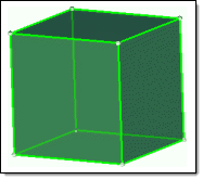
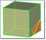
Green
Solid is mappable in three directions. This is very rare.
Figure 1. . The first cube is mappable in 3 directions, but if a corner is split
off it becomes mappable in only 1 direction, and the corner is not
mappable without further partitioning.
Partition solids for mappability.
Any solid edit operation will update the display of the solid entities
automatically.
Partitioning Solids for Mappability
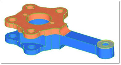
Figure 2
shows that one trim of the model by a single surface (the top surface of the
rectangular shaft, in this case) has created two additional solids within the model.
One solid remains in the ignored map state (blue), one is now not mappable (orange)
and one is one directional mappable (yellow - transparent).
Figure 2.
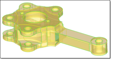
After additional partitioning the model using the tools found in the Solid
Edit panel, the model has transformed from having an ignored map and non-mappable
states to having only one directional and three directional mappable states. Figure 3 shows one three directional mappable solid, as
indicated by the green transparent solid at the base of the shaft where it joins the
part's main body. Figure 3.
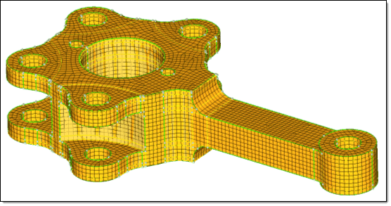
Once partitioning is successful, meshing can commence. Accessing the
Multi-Solids subpanel and selecting all of the solids, plus the required meshing
options, yields a complete 3D mesh for the entire complex part, as shown in Figure 4. Figure 4.
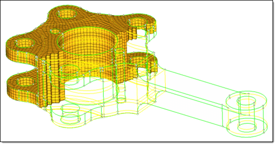
Selecting and masking a section of the elements confirms that the mesh is a
complete 3D mesh, as opposed to just a surface mesh, as shown in Figure 5. Figure 5.