Overview of the geometry cleanup and defeaturing parameter settings used to define
things such as washer layers around holes, defeaturing pinholes and solid holes, rows of
elements along fillets, and many other options.
Configure parameter settings using the Parameter Editor.
Parameter settings can be saved to a file, and loaded for subsequent editing.
Access
Go to Mesh > Param.
Figure 1.
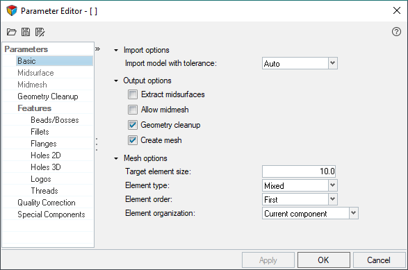
Basic
Basic parameters include importing, outputting, and meshing.
Import Options
Import model with tolerance
Tolerance value to be used while importing the CAD model.
Select Auto (recommended) to automatically
calculate the tolerance based on the type and dimensions of the
model.
Output Options
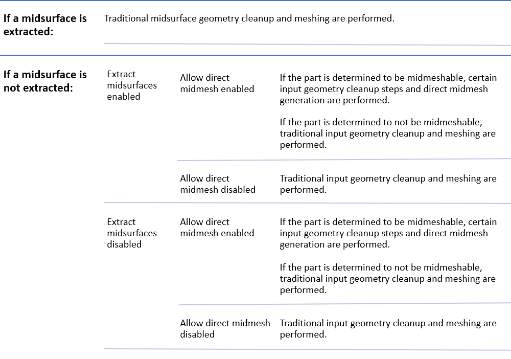
Extract midsurfaces
Select the Extract midsurfaces checkbox to
extract the midsurface before meshing using the selected extraction
method. Only the midsurface geometry is meshed and the original geometry
is deleted.
Note: Selecting this option activates the
Midsurface settings.
Allow midmesh
Select the Allow midmesh checkbox to create a
direct midmesh for the parts where midsurface extraction is difficult or
not possible, such as plastics, castings and machined
parts.
Note: Selecting this option activates the
Midmesh settings.
Geometry cleanup
Select the Geometry cleanup checkbox to enable
additional cleanup parameters that can be turned on and off
independently.
Note: Selecting this option activates the
Geometry Cleanup settings.
Create mesh
Selecting this option activates the Quality
Correction tab on the left.
Mesh Options
Target element size
Desired element size for meshing and optimization.
Note: The element size
defined here should match the ideal value for min length and max
length as defined in the criteria file. If this does not match,
BatchMesher may not be able to
produce meshes that adhere to the target quality
requirements.
Element type
Type of elements to create.
Element order
Create first or second order elements.
Element organization
Organize new elements in either the current component or the original
surface's component(s).
Midsurface
Midsurface parameters define the tasks that are performed by BatchMesher when extracting the midsurface.
Method
Select method to use when extracting the midsurface before meshing.
Sheet metal only
Only consider geometry for midsurface extraction that meets the user
defined settings for the options specific to sheet metal.
Note: If this
option is disabled, it will result in a time savings, but all parts
will be attempted to have a midsurface extracted.
Maximum thin solid thickness to width ratio
Maximum ratio between the approximate thickness of the thin solid part
(shortest dimension) and its approximate width (2nd shortest dimension).
This parameter is used to limit the midsurface extraction to parts for
which the thickness is clearly smaller than the length and width.
Maximum thin solid thickness
Ignore thin solids with a thickness less than the specified value during
midsurface extraction.
Minimum feature angle between the solid’s edge and its faces
Minimum angle used to distinguish top and bottom faces of a thin solid
from its sides. Angles less than the specified value will be treated as
if they were flat for purposes of midsurface extraction.
Pre-midsurface geometry cleanup
Perform geometry cleanup steps on the model before midsurface
extraction.
Midmesh
Midmesh parameters define settings used to create the midmesh.
Extract element size
The element size used while creating (extracting) midmesh.
Ignore flat edges
Do not imprint flat edges from the input geometry onto the midmesh.
Flatten connections
Align/flatten the midmesh at ribs/connections.
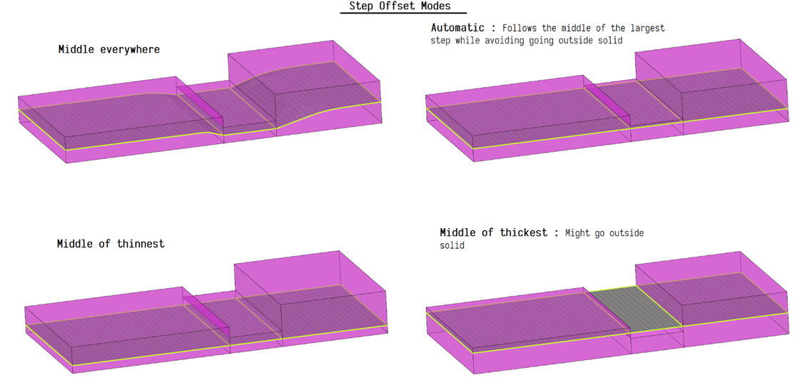
Step offset mode
This option allows finer control of how stepped geometry (one side
continuous surface, and opposite side steps) is captured. This option is
valid only when flatten connections is enabled. Values can be:
Automatic – Steps of different thickness across a
common base surface are automatically offset to a uniform distance from
the base surface.
Middle everywhere – Each step will be placed in
the middle everywhere.
Middle of thickest plate – All steps that share a
common base are moved to the middle of the thickest step. This might
place portions of the midmesh outside the solid.
Middle of thinnest plate – All steps that share a
common base are moved to the middle of the thinnest step.Figure 2.
Defeature openings with width <
Remove small holes and openings less than the specified width.
Suppress proximity edges factor
Remove 1D topology edges within the given factor of the minimum size
from the criteria file.
Combine non-manifold edges factor
Join non-manifold edges within the given factor of the minimum size from
the criteria file.
Defeature ribs width factor
The minimum size factor for removing small ribs. Ribs closer than this
factor times minimum size will be suppressed. Default is 0.9.
Figure 3.
Geometry Cleanup
Geometry Cleanup parameters define a variety of geometry feature recognition and
preparation tasks performed by BatchMesher.
The main tools for geometry cleanup include:
Flat feature suppression level, a curvature based feature suppression.
Suppress edges by proximity, allows to handle feature edges in close
proximity, generally based on minimum element size.
Controlling the above parameters can result in good feature capture with minimum
quality index failures. However, features are given more importance which might
increase the failed element count based on geometry and the cleanup parameter
values. It is important to define all of the settings appropriately.
Edges
Equivalence tolerance
Tolerance to use for equivalencing (stitching) edges, in conjunction
with the options below.
Auto
Calculate the tolerance internally.
<value>
Enter a tolerance. This is more useful when the auto
tolerance is not sufficient to make all of the necessary
connections.
Allow T-connections
Allow T-connections (non-manifold edges) to be created during the
stitching process.
Within components only
Allow stitching only within components. Stitching between edges of
different components is not allowed.
Surfaces
Delete duplicates
Define which duplicate surfaces to delete before meshing.
All
Consider all of the surfaces in all of the components
against each other.
Within components only
Consider all surfaces within components only. Duplicate
surfaces between components are not found.
None
Do not remove duplicate surfaces.
Tolerance
Define the tolerance used when finding duplicates.
All
Automatically calculate the tolerance from the model size
and other relevant geometric parameters.
<value>
Enter a tolerance. This is more useful when the auto
tolerance is not sufficient to find all of the
duplicates.
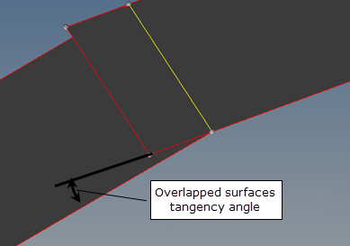
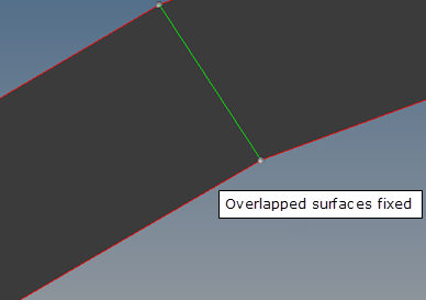
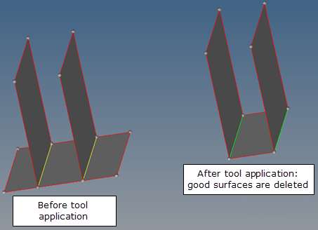
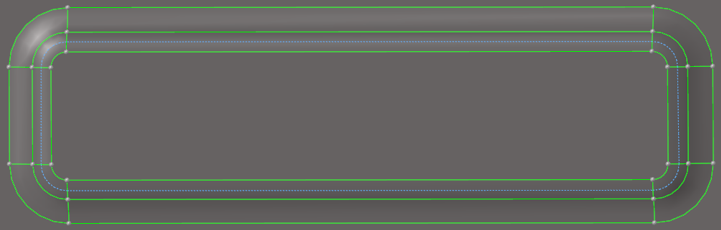
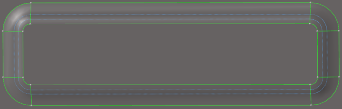
Fix overlaps with tangency angle <
Fix overlapping surfaces.
Auto
Calculate the tangency angle internally.
<value>
Enter a maximal tangency angle to fix overlapped
surfaces.
Figure 4. Overlapped Surfaces Tangency Angle
Figure 5. Overlapped Surfaces Fixed
Note: This option may remove the surfaces that should not be deleted.
For example, it may happen to surfaces with T-connections. Setting
the angle to < 45 may help reduce such side effects.
Figure 6. Possible Side Effects of Fixing Overlapped Surfaces
Component boundaries and feature edges
Preserve component boundaries
Do not suppress or remove components' boundary edges during geometry
cleanup, and do not move elements nodes across the components'
boundaries. In some cases, maintaining boundaries for adjacent
components that do not have any structural meaning would significantly
worsen the element quality results.
Suppress edges by proximity <
Suppress full or partial feature edges within the defined proximity
value.
This option allows geometry cleanup to consider a minimum element size
defined in the criteria file, which helps to avoid minimum size quality
failures. You can choose to enter an absolute value for proximity, or
you can choose to use the minimum element size or its factor.
When two or more feature edges come in proximity the following
guidelines or rules are used in general to determine which feature edge
gets suppressed to get more consistent and predictable results:
Full or partial feature edges within proximity are
suppressed. Figure 7.
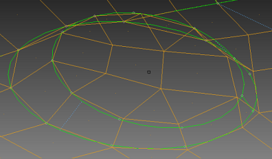
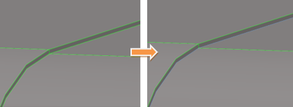
Feature edges that have higher curvature values are
retained. Figure 8.
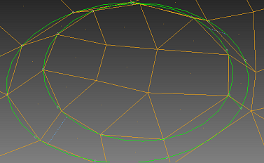
Boundary (free) edges are given priority. Figure 9.
Base and top feature edges are given a priority while doing
proximity cleanup for features like bead, bosses, and so on. Figure 10.
Note: The proximity value is generally kept less than the minimum
element size considering node movement tolerance.
Suppress sharp steps <
This option allows geometry cleanup to consider sharp steps if they are
failing the defined minimum element size. You can enter an absolute
value for proximity or you can use the minimum element size, or a
factor.Figure 11.
Note: Suppress edges by
proximity does not allow you to suppress sharp steps in proximity
unless this option is explicitly defined.
Flat feature suppression level
Suppresses feature edges based on curvature break angle. For the ease of
use, you can select a curvature break angle range, which varies from
very low to very
high.
Choose different levels of suppression from very
low to very high for more
flexibility and control over capturing feature edges. very
low suppression level corresponds to keeping maximum
feature edges, while very high suppression level
subjects the geometry to more feature edge suppression.
Note: The
user defined and recognized
features options are excluded from this suppression
to enable you to capture and protect important
features.
Figure 12. Flat feature suppression level: Very Low
Figure 13. Flat feature suppression level: Very High
Feature character size
The curvature break angle is calculated based on this setting.
Note: Available when Flat feature suppression level is set to
user defined.
Beads/Bosses
Geometry that represents beads on sheet metal parts is recognized.
Suppress beads: Heights <
Enable bead recognition and suppress any beads with a height less than
the specified value. This helps eliminate small elements and aids in
creating a good mesh flow.
Preserve rounded bead midline
If ON, the geometry trim at the peak will be created, suppressing other
top feature lines and capturing bead with nodes at the peak. Figure 14. Peak bead geometry captured with triangular
pattern
Note: If bead has geometry trim line at the top close to medial
position, that line could be used. If multiple trim lines are
present, based on the proximity, one of the trim lines could be kept
capturing peak of the bead.
If OFF, , the number of elements across the bead and the mesh pattern
are auto selected based on an element's chordal deviation and
permissible minimal element size. Based on these considerations, bead
peak geometry can be captured with trapezoidal mesh pattern. Figure 15.
Note: For sharp beads having medial geometry lines on the peak,
mesh line on the peak is still maintained capturing its geometry
though the original geometry trims might be suppressed.
Fillets
Recognize surface fillets and edge fillets.
Remove edge fillets with radius <
Square off any fillets/rounded edges located on free edges and having
radii below the specified value. This helps to create a good mesh
pattern in such areas. For concave fillets, this means material is
removed. For convex fillets, this means material is added.
Surface fillet recognition
Recognize surface fillets in order to perform one or more of the
following options:
Prevent the main (long) edges of the fillets from being
suppressed, and also prevent the nodes of those edges from
moving while fixing element quality.
Remove/defeature fillets. Gaps may result if complicated fillets
cannot be removed.
Split the fillets along the mid-line and suppress the
edges.
Specify the number of elements across the width of the fillets
for given fillet radii. The width value is defined as the arc
length of the fillet.
Specify the chordal deviation to be achieved while meshing.
A table becomes enabled to define a desired number of element rows for
specific ranges of average fillet radii, width, or both. Add/remove
element rows by clicking (Add Row) and (Remove Row). Figure 16.
Table 1. Surface Fillet Recognition Table Data
Column
Action
R>=
Minimum radius of the current fillet
range.
R<
Maximum radius of the current fillet
range.
W>=
Minimum width of the current fillet
range.
Method
Method used to treat fillets, such as remove,
split and suppress, and enforce rows.
Minimal Number of Rows
Number of elements across the width of the
fillets for a given fillet radius.
Max Chordal Deviation
Chordal deviation to be achieved while
meshing.
Uniform fillet strips with an average radius between 3 and 5 and an
average width between 2.0 to 9.0 will be meshed with one row of
elements; uniform fillet strips with an average radius between 5 and 20
and an average width between 9.0 to 16.0 will be meshed with two rows of
elements; and uniform fillets strips with an average radius between 20
and 30 and an average width between 16.0 to 24.0 will be meshed with
three rows of elements. This rule does not apply to fillets with an
average element width below or above the defined ranges of non-uniform
fillet strips (when minimal and maximal width of fillets exceed
30%).
If the width or number of rows columns in the surface fillet recognition
table are empty, the next default value will be applied. In this
example, that means uniform fillet strips with an average fillet width
between the element sizes of 0 to 2.0 will be meshed with one row of
elements.
A fillet can be meshed with enforced rows of elements, or split at its
midline and meshed accordingly based on element quality.
Minimize transitions
Allows mesh settings to be defined as an exact number of rows when the
checkbox is disabled.
This allows the Suppress tangency edges option to also become available.
When enabled, fillets are treated by making a midline and suppressing
the fillet itself. This combination may be selected to defeature very
narrow fillets. Midline splitting without suppressing tangency edges can
be used for wide fillets to ensure that the fillet mesh will be
symmetrical. Enabling Minimize transitions helps to reduce trias. The
mesh settings are then provided either as a minimum number of elements
and/or determined based on a maximum chordal deviation criterion.
BatchMesher calculates the required
number of elements as the maximum of the user-specified number of rows
and the number of elements required to meet the maximal chordal
deviation.
Note: The minimal element size and aspect ratio criteria
requirements are always honored. This means that the element quality
restrictions have the highest priority when calculating the element
density for a fillet range.
Flanges
Geometry that represents flanges on sheet metal parts is recognized.
Flange recognition
Flanges may be modified to suppress construction lines, subdivide them
into rectangular areas, or otherwise prepare them for proper meshing. As
this functionality is not supported for solid geometries, it should be
disabled for such models to improve performance.
Elements across flange width
Minimum number of elements to be created across the flange width.
Maximum width of flange
Maximum flange width to consider for flange recognition.
Minimum width of flange
Minimum flange width to consider for flange recognition.
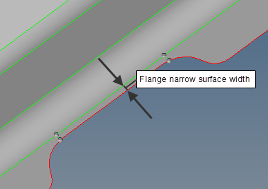
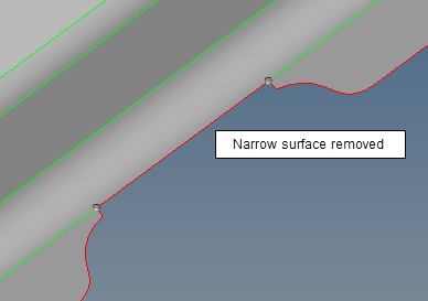
Delete flange narrow surfaces with width <
Controls the removal of narrow flange surfaces to avoid creation of
sliver elements and disruptions in the mesh flow.
Auto
Delete narrow flange surfaces when the maximal narrow
surface width is the minimum of 0.2*element_size and
min_element_size.
<value>
Delete narrow flange surfaces when the maximal narrow
surface width is the minimum of the specified value.
Figure 17. Flange Narrow Surface Width
Figure 18. Narrow Surface Removed
Holes 2D
Surface 2D holes are recognized and treated appropriately.
2D hole recognition
Surface holes of different sizes are recognized and treated
appropriately.
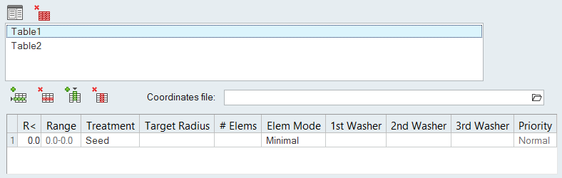
Surface hole recognition table data
Define radii ranges and additional options in the table.
Add/remove rows and columns by clicking: (Add Row), (Remove Row), (Add Column), (Remove Column). Figure 19.
Table 2. Surface Hole Recognition Table Data
Column
Action
R<
Maximum radius of the current hole range. The
minimum value is taken as 0.0 for the first row, or
as the maximum value from the previous row. For
slotted holes, the radius is measured at the tip of
the hole.
Range
Radius range for the current row. This value is
read-only.
Treatment
The manner in which you handle the following
options:
Seed
Elements around hole
Remove
Removes the found hole
Washer
Creates washers around the hole
Mark
Creates a node and tag at center of hole
Target Radius
Adjust holes in the range to have the specified
target radius. The radius can be specified as an
exact value, for example 5.0, or as an expression
based on the original radius, for example
radius*1.1, radius-0.5, radius+0.5.
# Elems
Enter the minimum/exact number of elements to
create around the holes, or set to
auto to automatically
select the number of elements so that the min and
max element size requirements are satisfied, with
the best possible representation of the hole shape.
Tip: Auto is not recommended for holes
with washer layers.
Elems Mode
Choose whether # Elems setting defines the
minimum or exact number of elements.
1st Washer/2nd Washer/3rd Washer
Sets the width of the first, second, third washer
as a constant value (select the blank entry in the
drop down and enter a value), a scale of the hole
radius, for example 0.6*radius, a subtraction
formula, for example 14.0-radius, or an automatic
determination based on element quality.
Priority
Set the priority of one radii range over the
others. For example, to ensure all bolt holes (radii
10-15) have correct washers but other holes are not
critical, holes with radii 10-15 will receive higher
priority than others. This ensures that if two holes
close to each other in the model have
overlapping/conflicting washers, the hole with
higher priority gets the washer while the other does
not, or the hole with the lower priority may get a
modified washer instead. In addition, when a hole is
set to high priority, washer elements are not
modified to correct for failed element quality. If a
hole is set to normal priority, washer nodes are
allowed to move to correct the quality.
Attempt to maintain narrow slot as
Rectangular ends – the slot ends are meshed to have rectangular
ends. Figure 20.
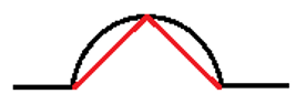
Rounded ends – the slot ends are meshed using the pattern
indicated in the following image. Figure 21.
Note: If this option is turned off, slot ends are meshed per the
parameters defined in the hole table.
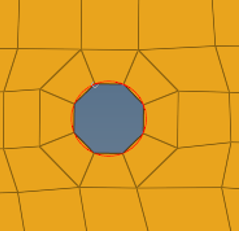
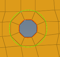
Add circumferential trim lines for washer
Keep geometry trim lines for washers.
Figure 22. Add circumferential trim lines for washer -
Off
Figure 23. Add circumferential trim lines for washer -
On
Suppress flanged holes with height <
Recognize holes with small downward flanges and eliminate those flanges
with a height less than the specified value. Flanges with a height less
than the minimal element size are extended to the minimal element size
if not removed.
Use file for hole recognition
Specify additional files containing X, Y, Z center locations of all of
the holes to consider.
Multiple files can be specified, each with their own definitions. The
order of the files determines the order of precedence in the case where
there are overlapping or conflicting definitions.
Click (Add Table) to add a new table for creating a
hole file. Click (Delete Table) to delete the specified hole
file table.
Figure 24.
This is useful for special treatment of specific holes, usually bolt
holes. BatchMesher compares the defined
locations to the holes in the model, and prioritizes the holes that
match. All of the options for Surface hole recognition are available for
these holes. If one or more holes files are defined, BatchMesher looks for the found holes in each
file, in the order the files are defined. If found, it applies the
washer table linked to the first found file to the corresponding holes.
If a hole is not found in any file, the settings from the default
general surface holes table are used.
The holes file must contain one line for each hole, with the values
either space, tab or comma separated. Each line contains a line number
followed by the X, Y, Z locations of each hole center.
Surface 2D holes are recognized and treated appropriately.
3D hole recognition
Surface holes of different sizes are recognized and treated
appropriately. A table becomes enabled to define the radii ranges and
additional options.
3D hole recognition table data
Define radii ranges and additional options in the table. Add/remove
element rows by clicking (Add Row) and (Remove Row). Figure 27.
Table 3. 3D Hole Recognition Table Data
Column
Action
R<
Maximum radius of the current hole range. The
minimum value is taken as 0.0 for the first row, or
as the maximum value from the previous row.
Range
Radius range for the current row. This value is
read-only.
Treatment
The manner in which you handle the following
options:
Seed
Elements around hole.
Remove
Removes the found hole.
Mark
Creates a node and tag at center of hole.
Remove and mark
Removes the found hole and creates a node and
tag at the center of the hole.
# Elems
Enter the minimum/exact number of elements to
create around the holes, or set to
auto to automatically
select the number of elements so that the min and
max element size requirements are satisfied, with
the best possible representation of the hole shape.
Tip: Auto is not recommended for holes
with washer layers.
Logos
Use the Logo Recognition parameters to remove small geometric features that represent
logos in the model design.
Remove logos
Recognize and remove small geometric features that represent logos.
Size <
Maximum size of a letter in the logo, as measured along/parallel to the
"shiny" surface.
Height <
Maximum height/depth of a letter in the logo, as measured normal to the
"shiny" surface.
Concavity factor
Creates a filter that provides more flexible control of automatic logo
recognition. As this is a heuristic tool, it may remove real features,
such as flat bottom round dimples, that were not intended for removal.
The Concavity factor is a quantitative measure of a letters shape
complexity, formally defined as:The contour_accumulated_turn_angle is the
sum of angles between a letters contour straight parts. Curved parts of
a contour letter are approximated by a segmented line composed of short
straight segments. For completely concave contour, such as circles,
quads, and hexagons, concavity factor contour_accumulated_turn_angle =
360 degrees and concavity factor = 0.
Tip: Extend the
recognition and removal of a logo by reducing the
Concavity factor.
Threads
Geometry that represents threads is recognized.
Remove threads
Recognizes and removes threads.
Depth <
Remove cylindrical or conical threads with a depth less than the
specified value, and replaces them with a smooth cylinder or cone
surface.
Replace removed threads with cylinder diameter
Method used to define the diameter of the replacing cylinder or cone.
autodecide
Automatically determine diameter based on the diameter of a
blank before thread cutting begins.
For inner (hole) threads, it corresponds to the thread minor
diameter. For outer (bold) threads, it corresponds to the
thread major diameter.
major
Use diameter of the thread major.
mean
Use diameter of the thread mean.
minor
Use diameter of the thread minor.
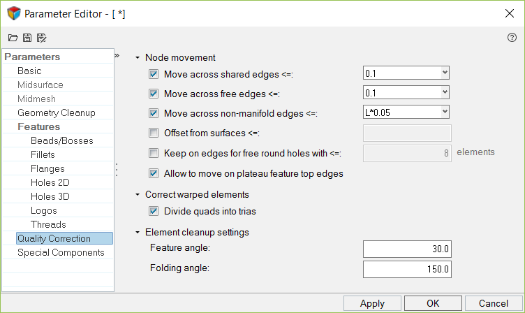
Quality Correction Parameter
Used by BatchMesher to generate a mesh on the cleaned-up
geometry.
Figure 28.
BatchMesher has a powerful mesh flow algorithm which
considers the shape of the geometry and aligns the mesh to create orthogonal meshes
automatically. It also helps to reduce number of trias and places them strategically
to avoid bad mesh patterns. BatchMesher is able to
control the average element size in order to generate a more uniform mesh.
These parameters control the behavior of the post-mesh element cleanup operations.
They are intended to fix elements failing the quality criteria, to reduce number of
tria elements for mixed/quad meshes, to correct bad mesh patterns, and to fix mesh
flow for fillets. All of the element cleanup operations are compliant with the
quality criteria, in that they should improve or at least not worsen the mesh
quality.
All element cleanup behaviors are based either on nodal movement (smoothing),
changing element connectivity (collapsing, splitting, and so on) or local
remeshing.
Node movement
Move across shared edges <=
Define the maximum distance to move nodes across shared edges to correct
the quality.
Move across free edges <=
Define the maximum distance to move nodes outside of free edges to
correct the quality.
Move across non-manifold edges <=
Move nodes away from the geometry's non-manifold edges by less than the
specified distance. Applies only to Rebuild Mesh.
Offset from surfaces <=
Move nodes off the geometry to correct warped elements.
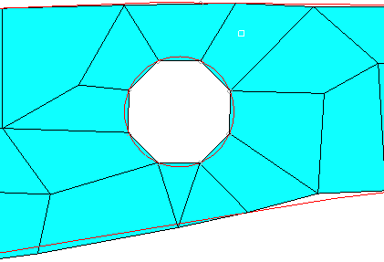
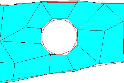
Keep on edges for free round holes with <=
Do not allow any nodes to move off the edges of free holes (without
washers) with less than a specified number of elements. This is useful
if distortion of the holes is not allowed.
Figure 29. Keep Nodes on Edges for Free Round Holes with
<= On
Figure 30. Keep Nodes on Edges for Free Round Holes with
<= Off
Allow to move on plateau feature top edges
Plateau feature top edge nodes are allowed to move to fix the failed
elements. Figure 31.
Figure 32. Allow Nodes to Move on Plateau Feature Top Edges
= On
Figure 33. Allow Nodes to Move on Plateau Feature Top Edges
= Off
Correct warped elements
Divide quads into trias
Split quads into trias to meet the element criteria defined in the
criteria file.
Element cleanup settings
Feature angle
Element feature angle to maintain while performing element cleanup.
Folding angle
Elements whose angle exceeds this value are considered folded over, and
BatchMesher attempts to clean them up.
Special Components
The Special component selection parameters define a method for selecting special
components.
Special component selection
Enable special component selection.
Selected components treatment
Provides options for meshing.
Mesh without geometry cleanup
Mesh the listed components but will not perform any geometry
cleanup on them before meshing. Any remaining components
that are not listed will be batch meshed using the normal
process, including geometry cleanup.
This is useful for models in which some components do not
require geometry cleanup but the rest might. Models in which
no components require cleanup can be batch meshed with the
Geometry Cleanup checkbox turned off.
Mesh and keep connectivity
Mesh the listed components while maintaining connectivity to
any existing mesh.
This is useful when components are to be meshed with
multiple element sizes but transitions at the common edges
of the different sizes are required. Each component should
be meshed individually with its own parameter and criteria
files with this option enabled.
Ignore and keep connectivity
Ignore the listed components while maintaining connectivity
to any existing mesh. The mesh and geometry of the ignored
components are not touched during batch meshing. The mesh
created on other adjacent components is connected to any
existing mesh on the ignored components.
This is useful for batch meshing of different components
with different criteria/parameters files, or when
pre-meshing components interactively or with some other
procedure, followed by batch meshing of other
components.
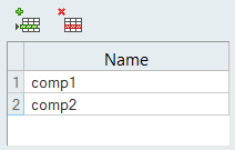
Selected components
A table becomes enabled to specify special components.
Add/remove components by clicking (Add Row) and (Remove Row). In the Name field,
enter component name. Figure 34.
As an example, a model may have two components named
front_10 and rear_20, which share common surface edges. The
component front_10 is to be meshed with element size 10 and
rear_20 with element size 20. This can be accomplished as
follows:
Create two sets of parameter/criteria files.
The first should have a target element size of
10 and the appropriate parameters. In this
parameter file, turn on the Special
component selection option,
Mesh and keep connectivity
sub-option, and add front_10 to the component
list.
The second file should have a target element
size of 20 and the appropriate parameters. In this
parameter file, turn on the Special
component selection option,
Mesh and keep connectivity
sub-option, and add rear_20 in the component
list.
Create a mesh type and assign the first set of
criteria and parameter files.
Create a second mesh type with the same name as the
first, and assign the second set of criteria and
parameter files.
Choose the geometry file to be batch meshed,
assigning it the mesh type from above, and submit
the job.
This will mesh front_10 first with the first mesh type,
and then take the results of this and mesh rear_20 with the
second mesh type, while maintaining connectivity with the
mesh created on front_10.
 Note: Suppress edges by proximity does not allow you to suppress sharp steps in proximity unless this option is explicitly defined.


 (Add Row) and
  (Remove Row).
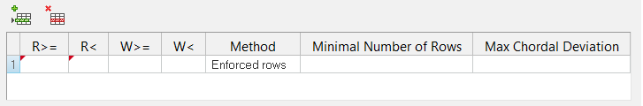
 (Add Column),
  (Remove Column).
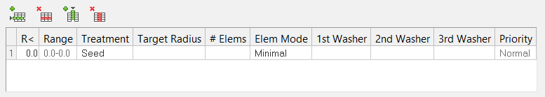
 (Add Table) to add a new table for creating a
hole file. Click
(Add Table) to add a new table for creating a
hole file. Click  (Delete Table) to delete the specified hole
file table.
(Delete Table) to delete the specified hole
file table.