Symmetry and Axisymmetry
Symmetry visualization allows partially modeled geometry to be shown in full extent by reflection and/or duplication or in the case of axisymmetric models, by 3D geometry generation.
The Symmetry dialog allows you to define options which can be used to visualize what a whole model would look like when you are modeling only a half, quarter, or a partial segment or as axisymmetric.
Symmetry Dialog
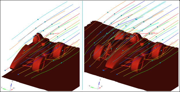
Figure 1. Example of a sports car half-model with streamlines and particle tracing displayed (on the left) and its symmetric reflection (on the right)
The Symmetry dialog allows you to define options which can be used to visualize what a whole model would look like when you are modeling only a half, quarter, or a partial segment or as axisymmetric. You can also select individual components for symmetry visualization, instead of an entire model. The visualization mode is valid for quasi-static, modal, and transient analyses animations, with any result plot (contour/vector/tensor/iso) also duplicated on the symmetric geometry. In addition, the mirror reflection and rectangular/circular array order can be controlled as relevant for the analysis. In the case of axisymmetric to 3D geometry, only the contour is copied from the original component onto the generated (swept) 3D geometry. Vector/Tensor/Iso are not applied.
To access the Symmetry dialog:
- From the Transform tools, click the Symmetry tool.

Figure 2.
The dialog contains two tabs: Symmetry and Axisymmetry.
Symmetry Tab
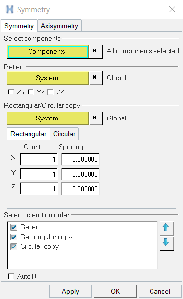
Figure 3. Symmetry dialog - Symmetry tab - Rectangular sub-tab
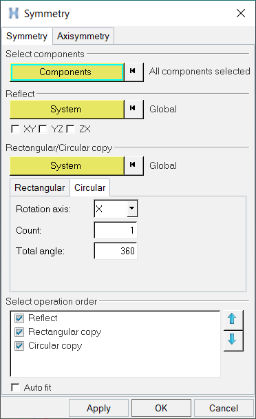
Figure 4. Symmetry dialog - Symmetry tab - Circular sub-tab
| Select components | Typically the entire model is reflected or copied, however component selection provides the flexibility to apply the visualization mode only on specific components. | |
| Components |
Use the Components input collector and the Extended Entity Selection Menu to select, or change, the components of the model to be reflected or copied. If no selection is made, all components of the model will be used by default. See Select Entities Using the Input Collector for more information on selecting entities. You can also pick components directly from the screen by clicking on the model display, or by using the Quick Window Selection selection method. The currently selected component is displayed to the right of the input collector. |
|
| Reflect | Generates a mirror image of the selected geometry across the plane of symmetry specified. Multiple planes of symmetry are supported, along with an option to specify a local coordinate system for the plane orientation. | |
| System |
Use the System input collector and the extended entity selection menu to select, or change, a local system to be reflected: Global or User Defined (Rectangular, Cylindrical, or Spherical). If no selection is made, the Global system will be used by default. See Select Entities Using the Input Collector for more information on selecting entities. You can also pick systems directly from the screen by clicking on the model display. The user-defined system, or any local system, is helpful in specifying the planes when the model set up is such that the planes of symmetry do not pass through the global origin or when they are not parallel to the global axis. The currently selected system is displayed to the right of the input collector. |
|
| XY/YZ/ZX | Use the various check boxes to determine the symmetry about any or all of the
XY, YZ, ZX planes (of the selected system). You can combine planes by selecting/checking multiple options. |
|
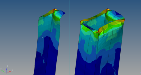 Figure 5. Example of a quarter model that is reflected across multiple planes to generate the full geometry |
||
| Rectangular/Circular copy | Generates geometry that is spaced in a rectangular or circular array. The number of copies and the direction in which the geometry is copied can also be controlled using the available options. | |
| System |
Use the System input collector and the extended entity selection menu to select, or change, a local system to be reflected: Global or User Defined (Rectangular, Cylindrical, or Spherical). If no selection is made, the Global system will be used by default. See Select Entities Using the Input Collector for more information on selecting entities. You can also pick systems directly from the screen by clicking on the model display. The orientation of the local system is more important than the origin for a rectangular copy. All the distances specified for separation are incremental distances from the model position. The currently selected system is displayed to the right of the input collector. |
|
| Count |
Input the number of rectangular copies to be displayed in each direction (X, Y, Z) using the specified spacing (see below). For example, if 2 is specified in the Count field for X, Y, and Z - then a total of 8 copies would be displayed (2 x 2 x 2). The number specified must be equal to or greater than 1. |
|
| Spacing (Rectangular) |
Specify the offset distance relative to the original location to be used. The spacing is the incremental distance from the current position. The direction of translation is obtained from the system selected. A negative number translates the geometry in the opposite direction of the axis. | |
| Rotational axis (Circular) |
Use the drop-down menu to determine if the reflection or copy will be displayed in the X, Y, or Z direction. | |
| Count (Circular) |
Input the number of circular copies to be displayed in angular sectors. Starting from zero degrees, the angular placement of subsequent sectors is (total angle/count). For example, if an analyzed sector spans 30 degrees and a Total angle of 90 degrees and a count of 3 is specified - then the first copy will be set at 0 degrees, the second copy at 30 degrees, and the third copy at 60 degrees. Or if the count = 3 and total angle = 180 - then the first copy is set at 0 degrees, the second copy at 60 degrees, and third copy at 120 degrees. |
|
| Total angle (Circular tab) |
Specify the offset distance (in degrees) relative to the original location to be used. See the explanation for Count (above) to better understand the relation between Total angle and the number of copies made. |
|
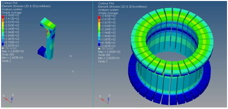 Figure 6. Example of a single component visualizing the symmetry 36 times in a circular copy to complete the ring |
||
| Select operation order | Allows you to control the application and order in which the operation(s) will be executed. To modify the operation order, click on the desired option (Reflect, Circular copy, or Rectangular copy) and use the blue arrows to move an operation up or down the list. The operations can be placed in any order - for example you can move copy before reflect, or reflect before copy, etc. | |
| Auto fit | Automatically adjusts the view so that model and duplicated geometry fit in the window. If this option is not selected, the view is not adjusted and portions of the reflected/copied symmetry could move out of the window | |
| Apply | Apply the settings/changes made to the symmetry. | |
| OK | Apply the settings/changes and exit the Symmetry dialog. | |
| Cancel | Disregard the settings/changes and exit the dialog. | |
Axisymmetry Tab
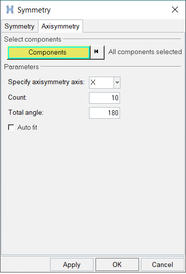
Figure 7.
| Select components | Typically the entire model is swept, however component selection provides the flexibility to apply the visualization mode only on specific components. | |
| Components |
Use the Components input collector and the extended entity selection menu to select, or change, the components of the model to be swept. If no selection is made, all components of the model will be used by default. See Select Entities Using the Input Collector for more information on selecting entities. You can also pick components directly from the screen by clicking on the model display, or by using the Quick Window Selection. The currently selected component is displayed to the right of the input collector. |
|
| Parameters | Specify parameters for generating 3D geometry from an axisymmetric component. | |
| Specify axisymmetry axis | Specify the axis of Axisymmetry for the model. The component will be swept about this axis and a 3-D geometry will be generated for visualization. | |
| Count | Specify the number of slices by which the 3D geometry will be divided. The default value is 10. | |
| Total angle | Specify the angle of sweep about the axis. Default value is 180. Positive and negative values can be entered and the sign will determine the direction of rotation. | |
| Apply | Apply the settings/changes made to the axisymmetry. | |
| OK | Apply the settings/changes and exit the Symmetry dialog. | |
| Cancel | Disregard the settings/changes and exit the dialog. | |
Additional HyperView Symmetry and Axisymmetry Visualization Considerations
- The Components and System collectors will retain their selections until they are reset.
- The Axisymmetric visualization mode is meant to be applied only on axisymmetric components.
- Axisymmetry, if defined, will be applied first to the selected component(s) before applying other symmetry operations, such as reflect or copy, which will be executed in the order specified.
- Components (geometry), Results (contour/vector/tensor plots), Explosion effects,
Section cuts, Added objects, and Tracing will all be reflected/copied onto the
duplicated geometry. In the case of Axisymmetry, the geometry along with any applied
contour will be swept onto a three dimensional shape. Note: In a few cases, when results are on nodes or on elemental corners, the contour on the face of the generated 3D geometry may differ from that on the original component. This is due to the differences in which HyperView renders a contour on 3D elements versus 2D elements.
- Notes, Measures, and Tracking systems are not affected and will not be duplicated; they will be displayed on the actual geometry only (not the reflective component).
- Highlighting/selecting entities on the duplicated geometry will also highlight/select the original entities on the actual geometry.
- Turning off a component in the Results Browser turns off that component for both the actual geometry and the reflective side or generated geometry (Axisymmetry). The duplicated geometry is for visualization purposes only; therefore there is no capability to separately turn it on/off using the Results browser.
- The Display Control menu can be used to quickly turn the symmetry and axisymmetry display on/off.
- Symmetry settings defined in one window can be applied to multiple windows and pages using the Apply Style option. When the active model is cut/copied and pasted using the context menu () all of the symmetry settings will be preserved.
- Symmetry is always defined on the active or current model. If there are multiple models overlaid in a window, the settings need to be applied on each on them individually. Explosion effects can be utilized in order to visualize any overlapping model geometry.
Reflect or Copy a Specific Component on a Model
-
From the Transform tools, click the Symmetry tool.
Figure 8.The Symmetry dialog is displayed.
Create a 3-D Visualization of an Axisymmetric Component
-
From the Transform tools, click the Symmetry tool.
Figure 9.The Symmetry dialog is displayed.