OptiStruct Flexbody Generation
MotionView generates an H3D flexbody neutral file directly from a Nastran or OptiStruct FEA input deck. The only FEA model preparation required is to identify the node IDs that will be used for interfacing and sensors.
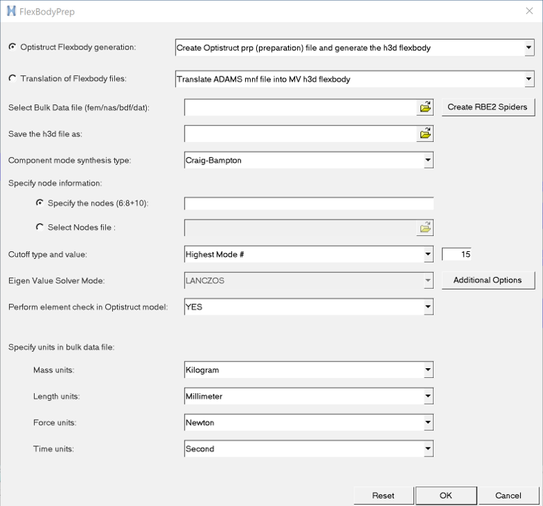
Figure 1. FlexBodyPrep Wizard – OptiStruct Flexbody Generation
| Create OptiStruct prp (preparation) file and generate the h3d flexbody | Select a OptiStruct file and process it to an H3D flexbody file. | ||
| Create OptiStruct prp (preparation) file | Select a OptiStruct file and convert it to an FEM file that is ready for flexbody generation. | ||
| When you select either of the above options, the following fields are displayed: | |||
| Select Bulk Data file (fem/nas/bdf/dat) | Select the OptiStruct source file that you want to convert. | ||
| Create RBE2 spiders | A utility to assist you with adding rigid spiders to
your original OptiStruct input file. Clicking this option will invoke HyperMesh and import the specified bulk data file. The Utility tab in HyperMesh can be used to generate RBE2 elements. |
||
| Save the *.h3d file as or Save the *prp file as |
Enter a filename and directory to which you want to save the H3D output file or the PRP file. The field displayed depends upon the conversion type you select. | ||
| Component mode synthesis type | Select one of the following options: | ||
| Craig-Bampton | Craig-Bampton obtains constrained eigen modes and static correction modes with a final orthonormalization step. | ||
| Craig-Chang | Craig-Chang obtains unconstrained eigen modes and a static analysis. | ||
| Craig-Bampton- Geometric-Stiffness | Uses the Craig-Bampton method with geometric stiffness to consider geometric
stress stiffening effects. See Comment 5 below. |
||
| Specify node information | Provide a list of interface nodes. You can identify
the nodes which will be candidates for interface nodes for the later step of MDL
implementation. It is important that only interface nodes and not sensor nodes be
identified at this point. Two options are available to provide this
information:
|
||
| Specify the nodes (6:8+10) | If this option is chosen, you can enter ranges, such as 4:12, or combinations, such as 4:12 +14. | ||
| Select Nodes file | This option is useful when there are a very large set of node numbers to be provided. The text file can contain a plain list of node numbers separated by a comma or space. The numbers can be provided in multiple lines. | ||
| Cutoff type and value | Select: Highest Mode # or Highest Frequency in 1/(time units) |
If Highest Mode # is selected, you must specify the number of constant eigen modes to be included in the flex body. Or you may select Highest Frequency in 1/(time units) to specify the highest frequency in the flexible body. | |
| Additional Options | Click to display the Additional Options dialog.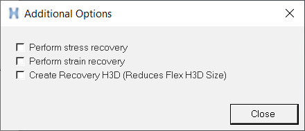 Figure 2. |
||
| Perform stress recovery | Check this option to have modal stresses computed and stored in the flex body H3D file. This option is needed to view stress for MBD simulation results in HyperView. | ||
|
Perform strain recovery |
Check this option to have modal strain computed and stored in the flex body H3D file. This option is needed to view strain for MBD simulation results in HyperView. | ||
| Create Recovery H3D (Reduces Flex H3D Size) | Check this option to reduce the model size by representing model as boundary
line elements (PLOTEL) and create a recovery h3d file. See Comment 7 below. |
||
| Perform element check in OptiStruct model | Controls whether or not OptiStruct will perform an element check of the model. | ||
| Specify units in Bulk Data File | Specify the set of units for mass, length, force,
and time that were used in the FEM file. For units to be consistent between the flexbody and the MDL model by which the flexbody is utilized, the units of the FEA model must be identified. This unit information is stored in the H3D file and all affected parameters in the solver flexbody matrix file are scaled accordingly. See the Comments section below for additional information regarding the types of units supported by FlexBodyPrep wizard. |
||
| Create h3d flexbody using pre-existing prp (preparation) file | Select an existing PRP file and use it to create an H3D file. | ||
| Select Pre-existing prp (preparation) file | Use the file browser to select the pre-existing PRP file that you want to use to create the H3D file. | ||
| Clear | Clear your selections and reset the wizard. | ||
| OK | After making your selections, click OK to have the wizard invoke OptiStruct and generate the flexible body H3D file. | ||
| Cancel | Exit the FlexBodyPrep wizard. | ||
Flexprep Operation - Specifics of the inputfile (fem/bdf) File
The FEM or BDF file that you specify as the input should have nodes, elements (including rigid elements), material, and property specifications.
Param statements are not required, but they are preserved. For example, wtmass is preserved, which causes the mass/inertia from OptiStruct to be scaled. Flexprep remembers the wtmass and scales them back. Cards not affecting element connectivity, node positions, and materials are ignored. These include super element cards, EIGRL card, SPC, and so on. Exterior points do not need to be specified in the BDF file since they are supplied separately from the bulk data file.
Flexprep Utilization of the Input File
The FlexBodyPrep wizard reads the bulk data file and prepares a file for OptiStruct flexbody creation called a preparation file (prp is appended to the original name). In this process, the model information such as nodes, elements, material and property cards from the input file are used. Other subcase information except MODEL and SET cards are not considered.
Additional cards such as CMSMETH ASET1, STRESS, STRAIN are added based on the inputs provided in the wizard dialog. The preparation file is then submitted to the through the flexprp batch utility, that in turn submits the job to OptiStruct solver, which invokes the component mode synthesis technique. As a final step, inertia shape integrals are calculated and properties are written to the H3D file.
The units in the H3D file are always in kg-mm-N-sec. Unit conversion occurs when writing to or reading from the H3D file whenever necessary.
Comments
- Other FEA input decks can be used by importing them into HyperMesh and exporting them to a OptiStruct file.
- By default, MotionView uses the same version of OptiStruct, but you can override this by using the -ospath command when running flexprep in batch mode
- The number of modes selected is a key contributor to MBD solver performance versus MBD solver accuracy. The higher modes provide the flexbody with the capability to take on shapes of tight curvature. However, these additional modes can greatly reduce the MBD solver performance. If you use the Stress option for OptiStruct generation of H3D flexbodies, please keep in mind that accurate representation of stress generally takes many more modes than accurate displacement (shape) representation.
- The first six modes are rigid body modes and when the resulting H3D is referenced by MDL, by default, these first six modes are not included in the solver deck or the flexbody matrix file.
- Flex body H3d generated using Craig Bampton – Geometric stiffness writes out GEOSTIFF blocks in addition to mode and mode shape information. You will have the option to include geometric stiffness effects during MBD solution in the Body panel.
- Geometric stiffening effects may be included for models such as slender beams where effects of deformation have significant effect on stiffness of the structure.
- Reduce the model size and generate recovery H3d This option can be used with very large models. Including this option creates a flex h3d with a smaller size due to reduction of model size as the model would be represented by line elements on the boundary (PLOTEL elements). A recovery H3d file would be generated that can be used along with OptiStruct after the MBD simulation to recover the detail results and further used in a fatigue simulation. Refer to the Recovering MBD Analysis results in OptiStruct section in the OptiStruct Flexible Body Generation topic.
- The following table shows the type of units supported by FlexBodyPrep wizard:
Mass Kilogram Gram MegaGram Pound_mass Slug Slinch Ounce_mass Kpound_mass Length Millimeter Inch Foot Mile Centimeter Meter Kilometer Force Newton Pound_force Ounce_force Kpound_Force Dyne Kilogram_Force Knewton Time Second Millisecond Hour Minute - Based on the selection, the DTI_UNITS card is written to the preparation file.
- OptiStruct supports many other type of units. Please refer to DTI, UNITS in the HyperWorks Solver Reference Guide for more details. If the FlexBody wizard does not have the units in which the FEM file is modeled, it is then recommended that the DTI_UNITS card be modified and submitted to the OptiStruct solver manually.