Import CAD or FE using HyperMesh
MotionView invokes HyperMesh in the background which imports the CAD into a component collector. The surfaces of the components are meshed and exported to a specified graphic H3D file for visualization in MotionView. Each component collector is brought into MotionView as a body, and the mass and inertia properties are determined on a unit density basis (provided HyperMesh is able to create a solid entity successfully). You then have the option to specify density for each body based on which the actual mass and inertia are assigned to the bodies. You also have to declare the unit of original file (CAD or FE) so that MotionView can calculate mass, inertia, and CG in the units set in MotionView.
The import tool also has a feature to launch HyperMesh, works interactively to mesh the surfaces as chosen, and select nodes that can be imported as points.
The steps below outline how to import a CAD or FE file using the Import CAD or FE using HyperMesh dialog.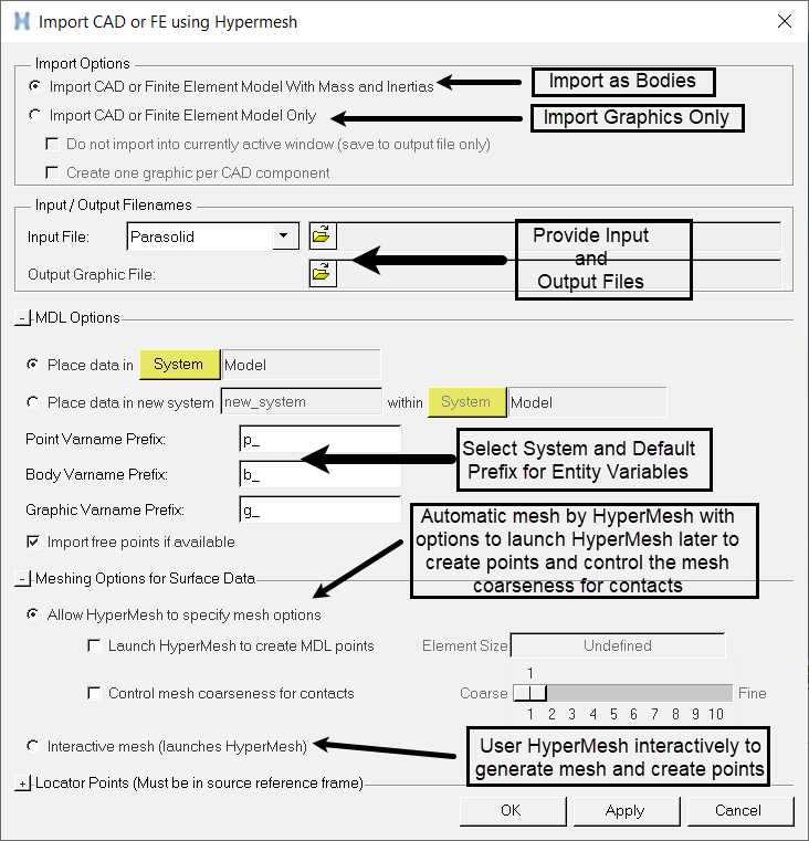
Figure 1. Import CAD or FE using HyperMesh Dialog
-
Specify the meshing options for the surface data.
- Allow HyperMesh to specify mesh options - Allow HyperMesh to mesh the surfaces with the default mesh options.
- Interactive mesh (launches Launches HyperMesh) - Launches HyperMesh with the source file loaded, which allows you to mesh as per your choice and macros to create MDL points.
If Allow HyperMesh to specify mesh options is selected, the following sub-options are available:- Launch HyperMesh to create MDL points - Launches HyperMesh specifically with a macro, allowing you to select FE nodes that will become MDL points.
- Control mesh coarseness for contacts - Activate
the check box to access options which allow you to control the mesh
coarseness for the contacts. Use the slider bar to adjust the mesh from
coarse to fine (1 - 10). The default setting is 5.
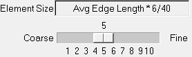
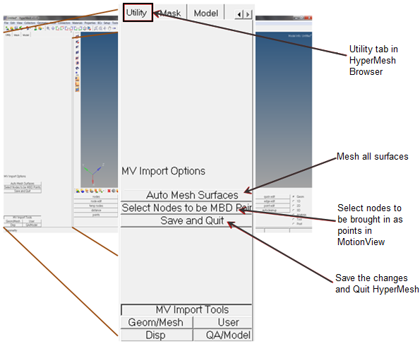
Figure 2.
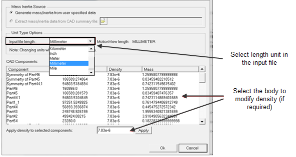
Figure 3.
- The following CAD/FE types are supported for the Import CAD/FE with
Mass/Inertia option:
Catia HyperMesh JT Nastran Optistruct Parasolid ProE SolidWorks STEP UG - The following additional CAD/FE types are supported for Import CAD/FE
only:
Abaqus ACIS Ansys DXF DXF HyperMesh Ascii Ideas IGES/IGS LS-Dyna Madymo Marc Pamcrash2G PDGS Permas Optistruct VDAFS - Some of the CAD formats like Catia and UG could need additional CAD reader license and library settings. Refer to CAD Reader Support for more details.
- The densities assigned are only applicable at the time of the import process, and they cannot be changed once the import is completed. The volume information will not be available until after the import process is complete.
- The accuracy and tolerance of mass/inertia and CG location for FE models can vary marginally based on the coarseness of the mesh.
- The mesh is used for graphic visualization only since this import is restricted to rigid bodies only. There are no quality requirements on the mesh.
- This interface works well for up to a medium size CAD assembly (~100 components). A very large CAD assembly import may encounter memory restrictions.