Flexbody Flow
Parts are meshed in HyperMesh to generate a Nastran Bulk Data file. You can directly supply the bulk data file or it can be translated from input files from other FE codes through HyperMesh.
When a bulk data file is read into the Flexbody Prep wizard, OptiStruct is automatically invoked to perform component mode synthesis.
- Bulk Data file name
- Force bearing node indices (the interface nodes)
- Modal synthesis type (Craig-Bampton, Free-Free, Frequency Response, Craig-Chang)
The resulting mode shapes for displacement, rotation, and stress tensors, as well as other data, is written to the flexbody H3D file. This file can be used in HyperView for animating mode shapes and stress contours.
After a mechanism is built in MotionView, you can switch rigid parts to flexible bodies by identifying and associating an H3D file with the particular part. The model definition file is written as a solver neutral MDL file. For flexible parts, you must specify a selected mode list and any additional sensory nodes indices per part in this stage.
When performing a dynamic analysis, MotionView creates the solver input file and generates the flexible body modal files (one per flexible part, for example, ADAMS’ MTX file) for the dynamics solver.
The results file from the solver, the H3D files, and the model definition file are needed for post-processing of flexible body mechanisms. The dynamic stress of the type of choice and other stress related indices are recovered automatically in the post processor for contour plotting as an integral part in the multi-body motion animation.
For result plotting, the analysis results can be read into HyperGraph via a template file that describes data layout for ASCII result file or through an external reader for binary files.
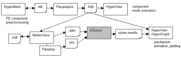
Figure 1. MODAL SYNTHESIS -> FLEX BODY DATA FLOW
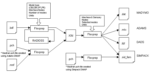
Figure 2.