HM-4300: Set Up an Abaqus Analysis in HyperMesh
In this tutorial you will setup an Abaqus analysis in HyperMesh.
- Load the Abaqus user profile and a model
- Define a material and properties, and assign them to a component
- View a *SOLID SECTION for solid elements
- Define *SPRING properties and create a component collector for them
- Create a *SPRING1 element
- Assign a property to selected elements
This exercise uses the abaqus3_0tutorial.hm file, which can be found in <hm.zip>/interfaces/abaqus/. Copy the file(s) from this directory to your working directory.
Load the User Profile and Model
In this step you will load the Abaqus user profile and model file.
When you load a user profile, HyperMesh opens the applicable utility menus, removes the unused panels, disables unneeded entities in the Find, Mask, Card and Reorder panels, and makes specific adaptations related to the Abaqus solver.
-
Open the model file by clicking from the menu bar, or by clicking
 on
the Standard toolbar.
on
the Standard toolbar.
-
In the Open Model dialog, open the file,
abaqus3_0tutorial.hm.
The model appears in the graphics area.
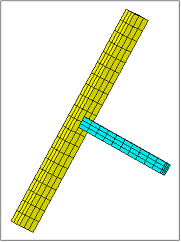
Figure 1.
Define the Material Properties
In this step you will define the material properties.
HyperMesh supports many different material models for Abaqus. In this step, you will create the basic *ELASTIC material model with no temperature variation. You will then assign the material to the property, which is assigned to a component collector.
-
In the Model Browser, right-click and select from the context menu.
HyperMesh creates and opens a material in the Entity Editor.
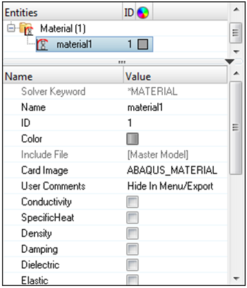
Figure 2.
Define the *SOLID SECTION Properties
In this step you will define the *SOLID SECTION properties.
-
In the Model Browser, right-click and select from the context menu.
HyperMesh creates and opens a property in the Entity Editor.
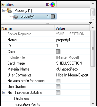
Figure 3. -
For Material Name, click Unspecified >> Material.
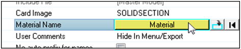
Figure 4. -
In the Select Material dialog, select
STEEL and then click OK.
HyperMesh assigns the material STEEL to the property Solid_Prop.
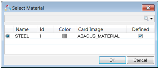
Figure 5.
Assign the Property
In this step you will assign the property to the component.
When a material is assigned to a property, when a property is assigned to a component, the material is automatically assigned as well.
-
In the Model Browser, Component
folder, select BEAM and
INDENTOR.
Note: You can select multiple components by pressing Ctrl while selecting components.
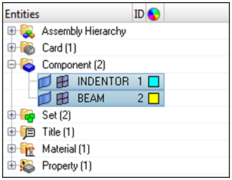
Figure 6. -
In the Assign to Component(s) dialog, select
Solid_Prop from the Property
list.
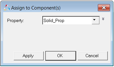
Figure 7.
View the Solid Elements
In this step you will view the *SOLID SECTION for solid elements.
HyperMesh supports sectional properties for all elements from the property collector.
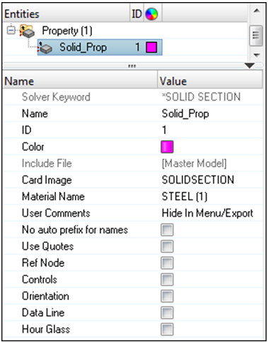
Figure 8.
Define the *SPRING Properties
In this step you will define the *SPRING properties.
In Abaqus contact problems, it is common to use grounded springs to provide stability to the solution in the first loading step.
Create a Component Collector
In this step you will create a component collector for the *SPRING property.
-
In the Model Browser, right-click and select from the context menu.
HyperMesh creates and opens a component in the Entity Editor.
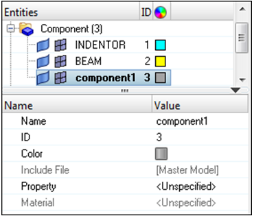
Figure 9. -
For Property, click Unspecified >> Property.
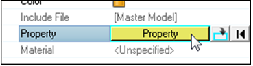
Figure 10. -
In the Select Property dialog, select
Spring_Prop and then click OK.
HyperMesh assigns the property Spring_Prop to the component GROUNDED.
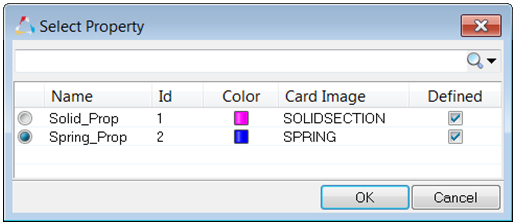
Figure 11.
Reset the View
In this step you will reset the view for further processing.
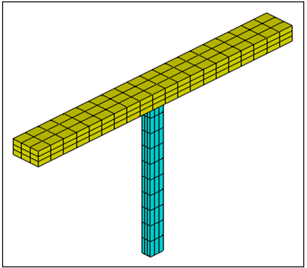
Figure 12.
Create the SPRING1 Element
In this step you will create the SPRING1 element.
-
In the id= field, type 451t460b3 and then press
Enter.
HyperMesh selects all nodes from 451 to 460 in increments of 3.
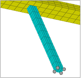
Figure 13. -
Click create. HyperMesh
creates SPRING1 elements.
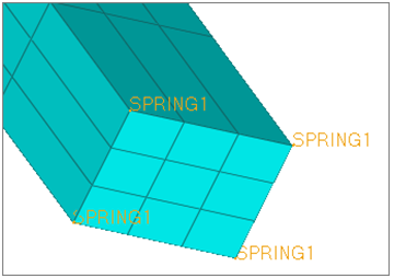
Figure 14.
Assign a Property to Selected Elements Overview
In most cases a property, for example, SHELL SECTION, SOLID SECTION, is assigned to a component collector. The elements belonging to the component collector assume the assigned property.
It is also possible in HyperMesh 11.0 to assign a property to individual elements without having to organize these elements in a separate component collector. A property can be assigned directly to selected elements. In this case, HyperMesh automatically creates an Abaqus element set (ELSET) for the selected elements and assigns the property to the ELSET.
HMprop_propertyname,
where propertyname is the name of the property collector that is
assigned to the elements. In the example below, a property collector called
property1 is created and assigned to elements 1. This information
is translated in the Abaqus
*.inp file
as:** Template: ABAQUS/STANDARD 3D
**
*NODE
1, 2.5 , 0.0 , 2.5
2, 2.5 , 0.0 , -2.5
3, -2.5 , 0.0 , -2.5
4, -2.5 , 0.0 , 2.5
**HWCOLOR COMP 1 11
*ELEMENT,TYPE=S4R,ELSET=auto1
1, 1, 2, 3, 4
*ELSET, ELSET=HMprop_property1
1
**HM set by property 11 22
*SHELL SECTION, ELSET=HMprop_property1, MATERIAL=The HMprop_ prefix can be suppressed in the property’s card image by selecting the
No_auto_prefix_for_names checkbox.
The comment **HM_set_by_property 11 is written by HyperMesh to the *.inp file so that the
element property definition and assignment are read properly when the
*.inp file is imported in HyperMesh. The number 11 refers to the color chosen for the property and 22 as the property
ID.
Create a Property
In this step you will create a property.
Assign a Property to Individual Elements
In this step you will assign a property to individual elements.
-
On the Standard Views toolbar, click
 .
.
-
In the graphics area, select the leftmost and rightmost layers of solid
elements belonging to the horizontal BEAM component.
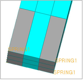
Figure 15. -
On the Visualization toolbar, select By Prop from the
Element Color Mode list.
HyperMesh colors the elements by their property assignment.
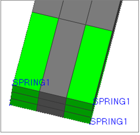
Figure 16.When a property is assigned to a component collector, HyperMesh writes out the comment *HM_comp_by_property to distinguish the component property assignment from that of individual element.