HM-1020: Work with Panels
A large portion of HyperMesh functionality is organized into panels. Many panels have common attributes and controls, so once you become familiar with the features of one panel, it is much easier to understand other panels.
- Use the entity selector and the extended entity selection menu to select and unselect nodes and elements from the graphics area.
- Use the orientation selector to define vectors along which to translate nodes and elements.
- Switch between different entities to select methods to define vectors.
- Toggle between two options.
- Enter, copy and paste, and calculate numbers.
- Use the rapid menu functionality to execute commands with the mouse buttons rather than clicking buttons.
- Interrupt, but not exit, a panel to go to another panel using the keyboard function keys.
- bumper.hm
Open and View Model Files
In this exercise you will open and view model files in HyperMesh.
- bumper.hm
Import IGES Model Files
In this exercise you will learn how to import IGES geometry files.
- bumper_end.iges
-
In the Import tab, click
 .
.
-
Click
 .
.
-
Click Import.
HyperMesh imports the IGES geometry data.
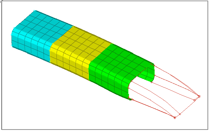
Figure 1.
Select Nodes in the Translate Panel
In this step you will use the Translate Panel to select nodes.
-
Click the entity selector to activate.
A cyan border around the entity selector indicates it is active.

Figure 2. -
This step is optional. If necessary, click
 on the Visualization toolbar to change the element
view style to wireframe.
on the Visualization toolbar to change the element
view style to wireframe.
-
In the graphics area, left-click on the corners of the elements to select a few
nodes.
HyperMesh positions a small, white node at each element corner you select.
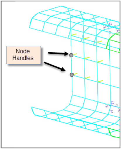
Figure 3. -
To reset the selection of nodes, click
 on
the entity selector.
on
the entity selector.
Import OptiStruct Input Files
In this exercise you will learn how to import OptiStruct input files into HyperMesh.
- bumper_end_rgd.fem
-
In the Import tab, click
 .
.
-
Click Import.
HyperMesh imports a mesh for the bumper's end portion to the geometry representing the bumper's end.

Figure 4.
Select Elements
In this step you will select and unselect elements from the graphics area.
-
Click
 on the entity selector and select
elems from the list of entities that can be
translated.
The entity selector is now set to elems.
on the entity selector and select
elems from the list of entities that can be
translated.
The entity selector is now set to elems.
Figure 5. -
In the graphics area, left-click on the element handles (the dot at the
element's center) to select several elements.
HyperMesh highlights the elements you select in white.
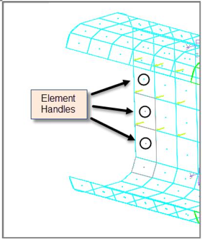
Figure 6.
Use the Quick Window Selection Method
In this step you will use the quick window selection method to select and unselect elements.
-
In the graphics area, press Shift + left-click to draw
a rectangular window around a few elements.
HyperMesh selects all of the element handles inside the rectangular window.
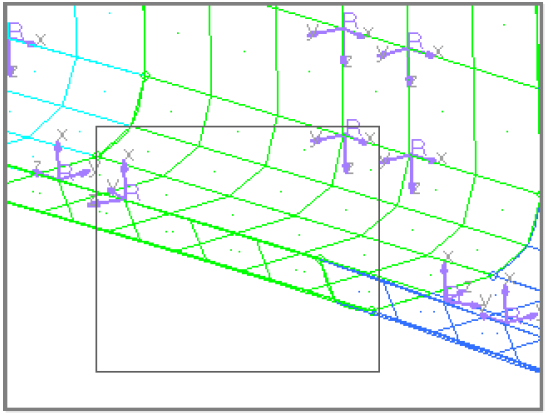
Figure 7. -
In the graphics area, press Shift + left-click.
The Quick window pop-up menu appears containing eight icons.
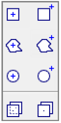
Figure 8. -
While still pressing Shift, click
 and draw a
polygon window around a few unselected elements.
and draw a
polygon window around a few unselected elements.
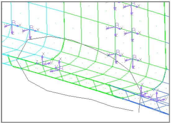
Figure 9.
Save a HyperMesh Session
In this exercise you will learn how to save a HyperMesh session to a model file.
- practice.hm
- From the menu bar, click .
- In the Save Model As dialog, navigate to your working directory and save the data in your current session as a binary data file labeled practice.hm.
Use the Extended Entity Selection Menu
In this exercise you will use the extended entity selection menu to select and unselect elements.
-
Click .
HyperMesh unselects the elements that you selected, and selects the elements that were not selected.
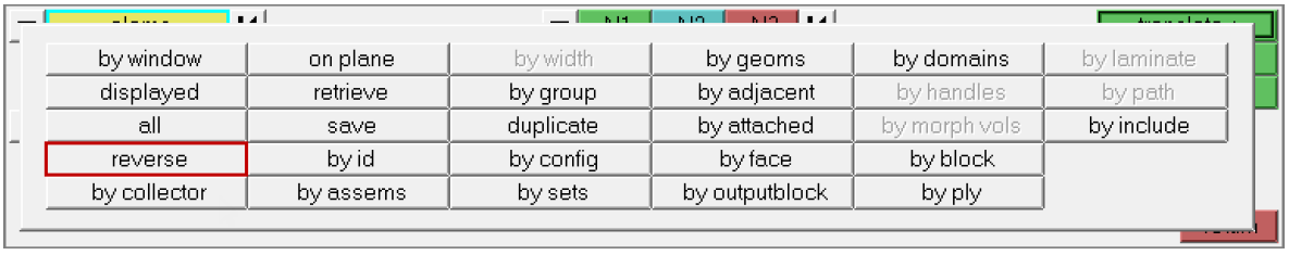
Figure 10. -
Click .
HyperMesh selects the elements that are adjacent to the selected elements.
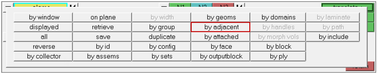
Figure 11.
Export Model Geometry
In this exercise you will learn how to export model geometry data to an IGES file.
- practice.iges
-
To access the Export tab, click from the menu bar or click
 on
the Standard toolbar.
on
the Standard toolbar.
Shade and Select Elements
In this exercise you will display elements in shaded mode.
-
On the Visualization toolbar, click
 .
HyperMesh displays the elements in shaded mode, rather than wireframe mode.
.
HyperMesh displays the elements in shaded mode, rather than wireframe mode.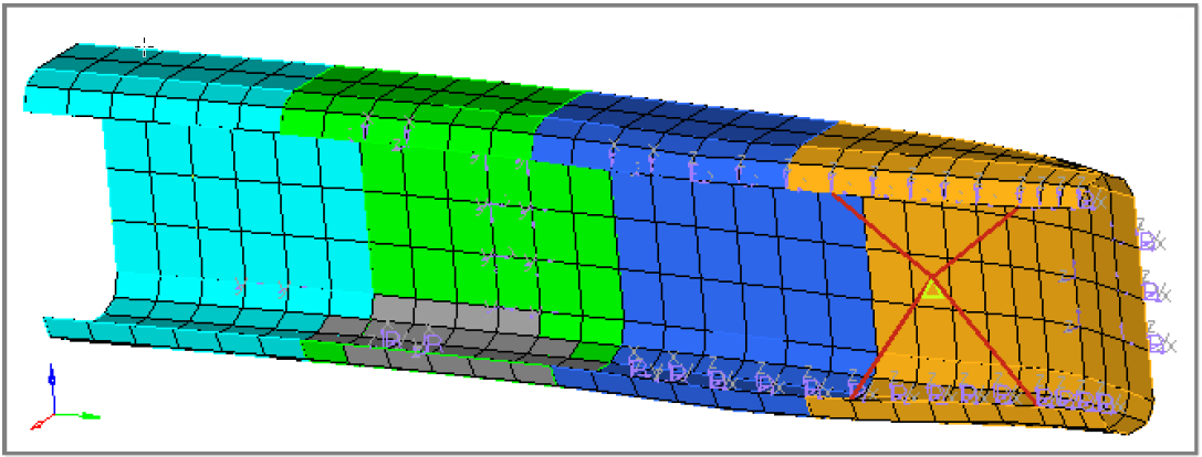
Figure 12. -
To clear the selection of elems, click on
the entity selector.
Export Model Data to an OptiStruct File
In this exercise you will learn how to model data to an OptiStruct input file.
- practice.fem
-
In the Export tab, click
 .
.
Specify Direction Vectors
In this step you will specify the direction vector along which to translate selected elements.
-
On the orientation selector, click and
select N1, N2, N3 from the list of vector and plane
options. These options define the direction in which to translate the selected
elements.

Figure 13. -
To activate the N1 selector, click
 .
The cyan border around the N1 selector indicates that it is active. Since the entity selector is no longer active, HyperMesh changes the color of the selected elements in the graphics area to gray.
.
The cyan border around the N1 selector indicates that it is active. Since the entity selector is no longer active, HyperMesh changes the color of the selected elements in the graphics area to gray.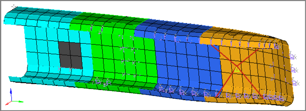
Figure 14. -
In the graphics area, select any node for N1.
HyperMesh highlights the selected node in green and the active selector advances to N2 in the Translate panel.
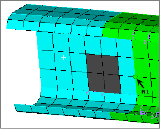
Figure 15.
Delete Model Data (Optional)
In this exercise you will delete all data from the current session.
This exercise is optional.
-
To open a new HyperMesh model, click from the menu bar, or click
 on the Standard
toolbar.
on the Standard
toolbar.
- In the HyperMesh dialog, click Yes if you would like to discard all current model data.
Specify a Translate Distance
In this step you will specify a distance to translate the selected elements and translate them.
-
Click the second toggle and select magnitude = N2-N1.
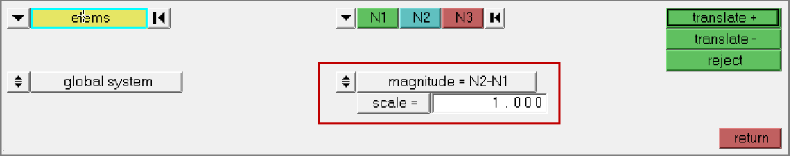
Figure 16.
Measure Distance Between Nodes
In this step you will measure the distance between two nodes.
-
In the graphics area, select any node for N1.
HyperMesh highlights the selected node in green, and the active selector advances to N2.
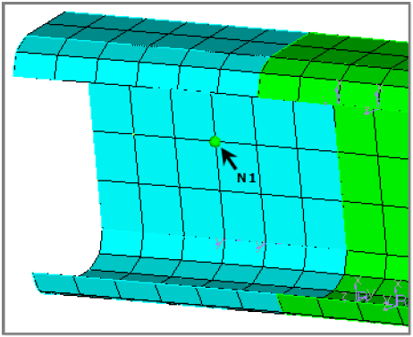
Figure 17. -
In the distance= field, highlight the value.
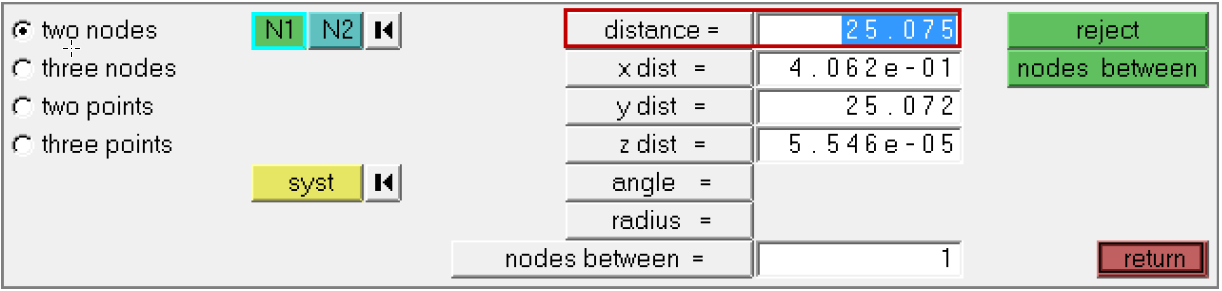
Figure 18.
Import IGES Geometry Files (Optional)
In this exercise you will learn how to import IGES geometry files.
- practice.igs
Import OptiStruct Input Files (Optional)
In this exercise you will learn how to import OptiStruct input files.
- practice.fem
Translate Selected Elements
In this step you will specify a distance to translate the selected elements and then translate them.
-
To past the distance= value that you copied from the Distance panel, press
Ctrl+V.
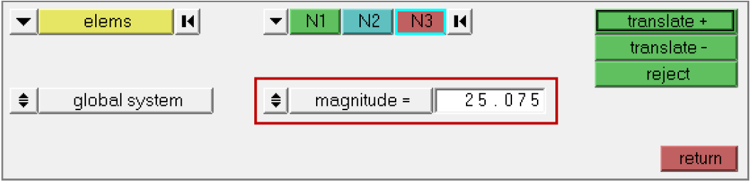
Figure 19.
Calculate the Value of Magnitude
In this step you will calculate and specify the value for magnitude.
-
Right-click in the magnitude = field.
The calculator appears.
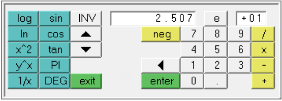
Figure 20.
Save Your Work (Optional)
With the completion of Steps 8, 9, and 10, your current session should contain all of the geometry and mesh data that existed in the session that you saved to a HyperMesh file.
This exercise is optional.
- From the menu bar, click .
Specify a New Vector
In this step you will specify a new vector and translate the elements.
-
To reset the direction of the translated elements, click on
the direction selector. N1 becomes the active selector.
-
In the graphics area, select three nodes for N1, N2, N3
to define a plane.
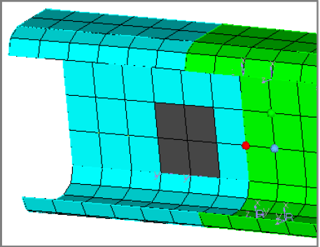
Figure 21. -
Click translate + or middle-mouse click.
HyperMesh translates the elements 57.75 units in the positive direction normal to the defined plane.
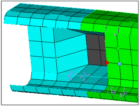
Figure 22.
Save Your Work
In this optional step, you will save your work.