Set Up an AcuSolve Input Deck
The following section describes the set up of an AcuSolve input deck within Engineering Solutions.
Import an Existing AcuSolve Model

Figure 1.
Load the CFD User Profile and Open the Solver Browser
-
Click the
 icon on the
Standard toolbar.
- Select in the User Profiles dialog.
- Click .
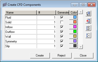
Create CFD Components
Set Up the Model in the Solver Browser
The Solver Browser can be used to set up a case to run CFD analysis using AcuSolve.
It is useful for setting up problems with simple boundary conditions. For more complex problems, export the model and set it up in AcuConsole.
| Global | This folder is used to define problems and set solver parameters for that problem. It contains the following sub folders: Nodal Initial Condition, Problem Description, Radiation Parameters and Solver Settings. The Problem Description folder contains utilities to set up the analysis type and solver models. Use the Solver Settings folder to define parameters related to selected analysis types and solver models. Initial condition can be defined in the Nodal Initial Condition folder. The radiation parameters for the model can be defined in the Radiation Parameters folder. |
| Output | Define the frequency of different outputs: Derived Quantity Output, Nodal Output and Restart Output. |
| Volumes | Components with Fluid and Solid card images are grouped in this folder. |
| Surfaces | Components with Inflow, Outflow, Wall, Slip, Symmetry and Far Field card images are grouped in this folder. |
| Components With No Card Image | Components with no card image will not be exported with the solver deck. By default, all of the components will not have a card image. You have to choose the appropriate card image for the component and the component will be moved to the Surfaces or Volumes folder accordingly. |
| Nodal Boundary Condition | Define boundary conditions on nodes apart from surface boundary conditions. |
| Materials | Define/edit the material model for CFD analysis. |
| Body Force | Define gravity and heat source for volume components. |
| Periodic Boundary Condition | Define periodic or axisymmetric boundaries along with the transformation definition. |
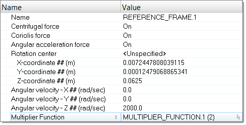
| Reference Frame | Define reference frames. |
| Mesh Motion | Define mesh motion. |
| Emissivity Model | Define emissivity model for radiation. |
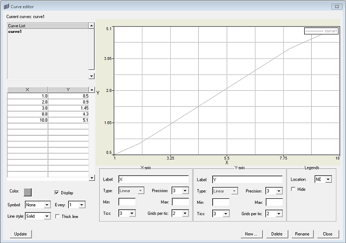
| Multiplier Function | Define multiplier functions to ramp up supported parameters. |
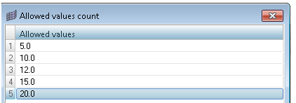
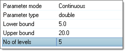
| Parameter | Parameters can be utilized to run solver parameter based
studies. For example, if you want to run a series of simulations with inlet velocity values of 0.5 m/s, 0.75 m/s, 1 m/s respectively, you can define a parameter on inlet velocity with the desired values. Using the HyperStudy Job Launcher DOE studies can be performed. |
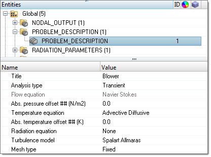
Figure 3.
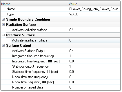
Define Component Type/Properties
Define Nodal Boundary Condition
This folder can be used to define boundary conditions on nodes apart from simple boundary conditions.
Create Material Model
The Materials entity is used to define/edit the material model for CFD analysis.
- Aluminum
- Air
- Water
Create Body Force
This folder can be used to define gravity and heat source for volume components.
Create Periodic Boundary Condition
This folder can be used to define periodic boundary condition.
Create Reference Frame
This folder can be used to define reference frames.
Create Mesh Motion
This folder can be used to define mesh motion.
Create Emissivity Model
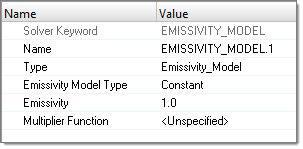
This folder can be used to define emissivity model for radiation.
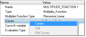
Create Multiplier Function
Create Parameter
This folder can be used to define parameters for Solver parameter based studies.
