Loads
Load management and configuration.
New Load Management
Introduction
Nastran and OptiStruct allow loading and boundary conditions to be defined on finite elements. These loads and boundary conditions are commonly applied as distributed loads. Because of their distributed nature, loads and boundary conditions must be carefully applied on individual FE elements. The repetitive nature of FE modeling development creates the overhead of applying loading and boundary conditions for each repetition of new mesh data. New load management aims to simplify this process and solve the problem of redefining loads.
Advantages
- Defining distributed values for loads defined on set entities
- Overhead creation and management of load entities on each FE location
- Dependency of FE locations for load creation
- Limitations of supporting complex boundary condition cards with multiple DOF definitions
- Consolidation of loads by common attributes such as SID, Magnitude, etc.
- Interrogation of loads is more powerful
- Advanced load option support:
- Applying pressure on Nodes
- Applying traction on axisymmetric elements
- Applying pressure on 1D elements based on element orientation
- Honoring solver recommendations such as Load on Set
- Enhancements to the Solver Browser to handle large numbers of loads
- A uniform way to set up a model (end-to-end) through the browser
Objectives
- Supporting region independent loads
- Defining distributed values for loads defined for each FE location in a set
- Adding complete support for all solver cards mapped to classic loads
Classic Load Absorption
Loads created from the panel are called classic loads. Although classic load entities are still supported, their use is not encouraged. New load management allows you to create loads from the Solver Browser. Using the "absorbloads" command, classic load entities can be absorbed into engineering entities.
Advanced Segregation
The advanced segregation feature allows you to spawn new engineering loads from existing engineering loads based on value distribution or topology. You can set up a single load with distributed values and run the "absorbentities" command to obtain multiple meaningful and manageable loads of the same magnitude value.
Realization
A realization command is provided for those who choose to work with classic loads. The "realizefieldloads" command creates classic loads from engineering loads, although it is not the exact reversal of the absorption command.
Load Visualization
- Vector Plots – display value distribution with the direction of the load
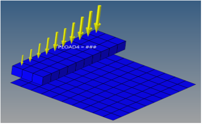
Figure 1. - Advanced Contour Plots – display value distribution with interactive filters
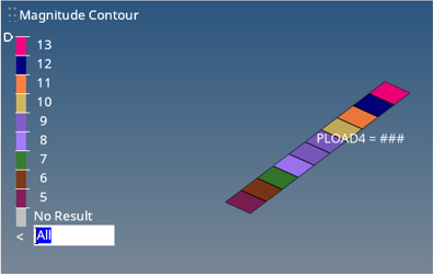
Figure 2. - Contour Plots – display value distribution with respect to the entire model
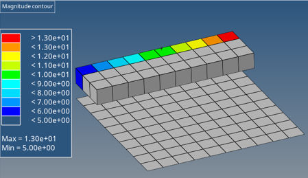
Figure 3.
Load values can be plotted at specific time stamps for curve-based time dependent loads.
Every load and constraint must be organized into one load collector, and therefore are mutually exclusive to a load collector.
Load Configurations
- Accelerations
-
Configuration 9 - Acceleration loads allow for an acceleration (length/time2) to be defined on the model.
Accelerations are displayed as a vector with the letter A at the tail end in the modeling window.
- Constraints
-
Configuration 3 - Constraints allow for constrained degrees of freedom to be defined on the model.
Constraints are displayed with a triangle that connects to the node, with the dof numbers that apply to the node beside the triangle in the modeling window.
- Fluxes
-
Configuration 6 - Flux loads are defined as an amount that flows through a unit area per unit time (amount/length2/time). Fluxes are typically used in modeling transport phenomena such as heat transfer, mass transfer, fluid dynamics, and electromagnetism.
Fluxes are displayed as a thick arrow labeled with the word "flux" in the modeling window.
- Forces
-
Configuration 1 - Force loads allow for a concentrated force (mass*length/time2) to be applied to the model.
Forces are displayed as a vector with the letter F at the tail end in the modeling window.
- Moments
-
Configuration 2 - Moment loads allow for a concentrated moment (length*force) to be applied to the model.
Moments are displayed with a double-headed vector with the letter M at the tail end in the modeling window.
- Pressures
-
Configuration 4 - Pressure loads allow for a pressure (force*length2) to be applied to the model.
For most solvers, the pressure load is considered as force/area, therefore the magnitude of the pressure is multiplied by the calculated area of the elements to which it is applied and resolved as concentrated force loads at the associated nodes.
Pressures are displayed as a vector with the letter P at the tail end in the modeling window.
- Temperatures
-
Configuration 5 - Temperature loads allow for a concentrated temperature to be applied to the model.
Temperatures are displayed as a vertical line with the letter T at the top in the modeling window.
- Velocities
-
Configuration 8 - Velocity loads allow for a velocity (length/time) to be applied to the model.
Velocities are displayed as a vector with the letter V at the tail end in the modeling window.
Abaqus Cards
| Card | Supported Load Types | Description |
|---|---|---|
| *BASE MOTION | Constraint | Defines scale factor and DOF for dynamic loads. |
| *BOUNDARY (electric potential, dof 9) | Flux | Specifies flux boundary conditions for piezoelectric analysis. |
| *BOUNDARY (structural) | Constraint | Creates structural boundary conditions. |
|
*BOUNDARY (temperature, dof 11) |
Temperatures | Specifies temperature boundary conditions. |
| *CECHARGE | Flux | Specifies concentrated electric charges for piezoelectric analysis. |
| *CECURRENT | Flux | Specifies concentrated current in electric conduction. |
| *CFLUX | Flux | Specify concentrated fluxes in heat transfer or mass diffusion analyses. |
| *CLOAD | Force | Creates concentrated forces. |
| *CLOAD | Moment | Creates concentrated moments. |
| *COUPLING | Constraint | Define a surface-based coupling constraint |
| *DECHARGE | Pressure | Distributes electric charges for piezoelectric analysis. |
| *DFLUX | Pressure | Specify distributed fluxes in heat transfer or mass diffusion analyses. |
| *DISTRIBUTING | Constraint | Define a distributing coupling constraint |
| *DISTRIBUTING COUPLING | Elements | Specify nodes and weighting for distributing coupling elements |
| *DLOAD | Pressure | Specifies distributed loads |
| *FILM | Pressure | Define film coefficients and associated sink temperatures. |
| *KINEMATIC | Multi-point Constraints | Define a kinematic coupling constraint |
| *KINEMATIC COUPLING | Multi-point Constraints | Constrain all or specific degrees of freedom of a set of nodes to the rigid body motion of a reference node |
| *MPC | Multi-point Constraints | Define multi-point constraints |
| *RADIATE | Pressure | Specify radiation conditions in heat transfer analyses |
| *TEMPERATURE | Temperature | Specifies predefined temperature field. |
ANSYS Cards
| Card | Supported Load Types | Description |
|---|---|---|
| BF | Flux | Defines a nodal body force load. |
| BF_FLUE | Flux | |
| BF_HGEN | Flux | |
| BF_TEMP | Temperatures | |
| BFE_FLUE | Flux | Defines an element body force load. |
| BFE_HGEN | Flux | |
| BFE_TEMP | Flux | |
| CE_STRUCT | Equation | |
| CE_THERM | Equation | |
| CE_MAG | Equation | |
| CE_ELEC | Equation | |
| ConvBulkTe | Pressure | |
| ConvFilmCo | Pressure | |
| D_A | Constraint | Vector magnetic potential. |
| D_CONSTRNT | Constraint | Defines DOF constraints at nodes. |
| D_MAG | Constraint | Scalar magnetic potential. |
| D_PRES | Constraint | |
| D_TEMP | Temperature | |
| D_VOLT | Constraint | |
| F_FLOW | Flux | Specifies force loads at nodes. |
| F_HEAT | Flux | |
| FLOTRAN | Pressure | Specifies "FLOTRAN data settings" as the subsequent status
topic. Note: FLOTRAN surface load label “FSI [fluid-structure interaction flag]”
is available under pressure load.
You must use DOF1 to add value for this label. |
| FORCE | Force | Selects the element nodal force type for output. |
| FORCE2 | Moment | |
| FSI | Pressure | |
| HFLUX | Pressure | |
| IC_A | Constraint | |
| IC_CONSTRN | Constraint | Specifies initial conditions at nodes. |
| IC_MAG | Constraint | |
| IC_PRES | Constraint | |
| IC_TEMP | Temperature | |
| IC_VOLT | Constraint | |
| PRESSURE | Pressure | |
| RDSF_EMI | Pressure | |
| RDSF_ENCL | Pressure | |
| SFE |
|
Defines elemental surface load. Note: Structural, thermal and Fluid labels are
covered.
|
| SFE |
|
Surface load
|
LS-DYNA Cards
Several load types cause three cards to be output for x, y, and z components. During input, these are grouped into one load. Loads cannot be applied to sets, components, or boxes. Load curves are input and output. Use the Card Editor to select load curves. Unless mentioned in the Notes column, load cards cannot be edited.
| Card | Supported Load Types | Description |
|---|---|---|
| *BOUNDARY_PRESCRIBED_MOTION_NODE | Constraints
|
Define an imposed nodal motion (velocity, acceleration, or displacement) on a
node or a set of nodes. DOF 4, -4, 8, -8, 9, -9, 10, -10, 11, -11 are not supported. |
| *BOUNDARY_PRESCRIBED_MOTION_NODE | Velocity
|
Define an imposed nodal motion (velocity, acceleration, or displacement) on a
node or a set of nodes. DOF 4, -4, 8, -8, 9, -9, 10, -10, 11, -11 are not supported |
| *BOUNDARY_PRESCRIBED_MOTION_NODE | Acceleration
|
Define an imposed nodal motion (velocity, acceleration, or displacement) on a
node or a set of nodes. DOF 4, -4, 8, -8, 9, -9, 10, -10, 11, -11 are not supported |
| *BOUNDARY_PRESCRIBED_MOTION_NODE_(ID) | Velocity | |
| *BOUNDARY_PRESCRIBED_MOTION_NODE_(ID) | Constraints
|
|
| *BOUNDARY_PRESCRIBED_MOTION_RIGID |
|
Define an imposed nodal motion (velocity, acceleration, or displacement) on a
node or a set of nodes. RIGID_LOCAL and _SET options are supported. |
| *BOUNDARY_PRESCRIBED_MOTION_RIGID_ID |
|
Define an imposed nodal motion (velocity, acceleration, or displacement) on a node or a set of nodes. |
| *BOUNDARY_PRESCRIBED_MOTION_RIGID_LOCAL |
|
|
| *BOUNDARY_PRESCRIBED_MOTION_RIGID_LOCAL_ID |
|
|
| *BOUNDARY_PRESCRIBED_MOTION_SET |
|
Define an imposed nodal motion (velocity, acceleration, or displacement) on a node or a set of nodes. |
| *BOUNDARY_PRESCRIBED_MOTION_SET_ID |
|
|
| *BOUNDARY_SPC_NODE | Constraints
|
Define nodal single point constraint |
| *BOUNDARY_SPC_NODE_(ID) | Constraints
|
|
| *BOUNDARY_TEMPERATURE_NODE | Temperature
|
Define temperature boundary conditions for a thermal or coupled thermal/structural analysis. |
| *CONSTRAINED_GLOBAL | Constraints | Define a global boundary constraint plane. |
| *INITIAL_TEMPERATURE_NODE | Temperatures LOC |
Define initial nodal point temperatures using nodal set IDs or node number.s |
| *INITIAL_VELOCITY |
|
Define initial nodal point translational velocities using nodal set
IDs. For structured output, global velocity is set to 0.0. For structured input, non-zero values for INITV = 1 or INITV = 5 create velocities. INITV values of 2, 4, 6, and 7 are ignored. |
| *INITIAL_VELOCITY_NODE | Rotation | Define initial nodal point velocities for a node. |
| *LOAD_BEAM_ELEMENT | Pressure | Defines load on beam elements |
| *LOAD_MASK | N/A | Apply a distributed pressure load over a three-dimensional shell part |
| *LOAD_NODE_POINT | Force
|
Apply a concentrated nodal force to a node or a set of nodes. LS-DYNA Load Configs 1, 2, 3 and 4 A load curve can be selected for these loads. |
| *LOAD_NODE_POINT | Moment
|
Apply a concentrated nodal force to a node or a set of nodes. LS-DYNA Load Configs 5, 6 7 and 8. |
| *LOAD_SEGMENT | Pressure
|
Apply the distributed pressure load over one triangular or quadrilateral segment defined by four, six or eight nodes. |
| *LOAD_SEGMENT_ID | Pressure
|
Apply the distributed pressure load over one triangular or quadrilateral segment defined by four, six or eight nodes. |
| *LOAD_SHELL_ELEMENT | Pressure
|
Apply the distributed pressure load over one shell element or shell element set. |
| *LOAD_SHELL_ELEMENT_ID | Pressure
|
Apply the distributed pressure load over one shell element or shell element set. |
| *LOAD_SHELL_PRESSURE | Pressure
|
Apply the distributed pressure load over one shell element or shell element set. |
| *LOAD_THERMAL_CONSTANT_NODE | Temperature N/A |
Define nodal sets giving the temperature that remains constant for the duration of the calculation. |
| *LOAD_THERMAL_VARIABLE_NODE | Temperature
|
Define nodal temperature that is variable during the calculation. |
Nastran Cards
| Card | Supported Load Types | Description |
|---|---|---|
| ASET | Constraints | Defines degrees-of-freedom in the analysis set (a-set) |
| ASET1 | Constraints | Defines degrees-of-freedom in the analysis set (a-set) |
| BNDFIX1 | Constraints | Defines analysis set (a-set) degrees-of-freedom to be fixed (b-set) during generalized dynamic reduction or component mode synthesis calculations. |
| BOLTFOR | Flux | |
| BSET1 | Constraints | Defines analysis set (a-set) degrees-of-freedom to be fixed (b-set) during generalized dynamic reduction or component mode synthesis calculations. |
| CSET1 | Constraints | Defines analysis set (a-set) degrees-of-freedom to be free (c-set) during generalized dynamic reduction or component modes calculations. |
| DAREA | Constraints | Defines scale (area) factors for static and dynamic loads. In dynamic analysis, DAREA is used in conjunction with RLOADi and TLOADi entries. |
| DEFORM | Flux | Defines enforced axial deformation for one-dimensional elements for use in statics problems. |
| FORCE | Force | Requests the form and type of element force output or particle velocity output in coupled fluid-structural analysis. |
| MOMENT | Moment | Defines a static concentrated moment at a grid point by specifying a scale factor and a vector that determines the direction. |
| OMIT1 | Constraints | Defines degrees-of-freedom to be excluded (o-set) from the analysis set (a-set). |
| PLOAD | Pressure | Defines a uniform static pressure load on a triangular or quadrilateral surface comprised of surface elements and/or the faces of solid elements. |
| PLOAD1 | Pressure | Defines concentrated, uniformly distributed, or linearly distributed applied loads to the CBAR or CBEAM elements at user-chosen points along the axis. |
| PLOAD2 | Pressure | Defines a uniform static pressure load applied to CQUAD4, CSHEAR, or CTRIA3
two-dimensional elements. The THRU field is supported for feinput only. On export, additional pressure cards for the range specified are written. |
| PLOAD4 | Pressure | Defines a pressure load on a face of a CHEXA, CPENTA, CTETRA, CTRIA3, CTRIA6,
CTRIAR, CQUAD4, CQUAD8, or CQUADR element. The THRU field is supported for feinput only. On export, additional pressure cards for the range specified are written. Unequal nodal pressures are now supported. The average pressure value is used as the magnitude of the pressure for visualization only. The individual field values, P1-P4, can be viewed or edited using the card editor. Updating the magnitude of pressure from the Pressures panel will have no effect on PLOAD4 cards defined using unequal nodal pressures. |
| QBDY1 | Flux | Defines a uniform heat flux into CHBDYj elements. |
| QSET1 | Constraints | Defines generalized degrees-of-freedom (q-set) to be used for generalized dynamic reduction or component mode synthesis. |
| QVOL | Flux | Volume Heat Addition - Defines a rate of volumetric heat addition in a conduction element. |
| SPC | Constraints | Defines a set of single-point constraints and enforced motion (enforced
displacements in static analysis and enforced displacements, velocities or
acceleration in dynamic analysis). Constraints on nodes are supported through SPC cards. PS field in GRID card is not supported. Upon import, any PS entry on the GRID card will be converted into an SPC card. |
| SPC1 | Constraints | Defines a set of single-point constraints. Supported for feinput only. On export, equivalent SPC cards are written. Alternate format with THRU in the fifth field is supported. |
| SPCD | Constraints | Defines an enforced displacement value for static analysis and an enforced motion value (displacement, velocity or acceleration) in dynamic analysis. |
| SUPORT | Constraints | Defines determinate reaction degrees-of-freedom in a free body. |
| SUPORT1 | Constraints | Defines determinate reaction degrees-of-freedom (r-set) in a free body-analysis. SUPORT1 must be requested by the SUPORT1 Case Control command. |
| TIC(D) | Constraints | Transient Initial Condition - Defines values for the initial conditions of variables used in structural transient analysis. |
| TIC(V) | Constraints | Transient Initial Condition - Defines values for the initial conditions of variables used in structural transient analysis. |
| TEMP | Temperatures | Defines temperature at grid points for determination of thermal loading, temperature-dependent material properties, or stress recovery. |
| TEMPBC | Temperatures | Defines the temperature boundary conditions for heat transfer analysis. |
| USET | Constraints | Defines a degree-of-freedom set. |
| USET1 | Constraints | Defines a degrees-of-freedom set. |
OptiStruct Cards
General boundary conditions, such as loads and constraints, should not be collected into specific load collectors. Organizing loads and constraints into a specific load collector may result in an error termination.
| Card | Supported Load Types | Description |
|---|---|---|
| ASET | Constraints | Defines the boundary degrees-of-freedom of a superelement assembly for matrix reduction. |
| ASET1 | Constraints | Defines the boundary degrees-of-freedom of a superelement assembly for matrix reduction. |
| DAREA | Constraints | Defines scale (area) factors for dynamic loads. DAREA is used in conjunction with RLOAD1, RLOAD2, TLOAD1, and TLOAD2 entries. |
| DELAY | Constraints | Defines the time delay term τ in the equations of the dynamic loading function. DELAY is used in conjunction with RLOAD1, RLOAD2, TLOAD1, and TLOAD2 entries. |
| DEFORM | Flux | Defines enforced axial deformation for one-dimensional elements for use in statics problems. |
| DPHASE | Constraints | Defines the phase lead term in the equation of the dynamic loading function. DPHASE is used in conjunction with RLOAD1 and RLOAD2 entries. |
| FORCE | Force | Defines a static force at a grid point or a SET of grid points by specifying a vector. |
| FORCE1 | Force | Used to define a static force by specification of a value and two grid points that determine the direction. It can also be used to define the EXCITEID field (Amplitude "A") of dynamic loads in RLOAD1, RLOAD2, TLOAD1 and TLOAD2 Bulk Data Entries. Additionally, the FORCE1 entry can be defined as Follower Loads in Large Displacement Nonlinear Analysis. |
| MBFRC | Force | Defines a constant force at a grid point by specifying a vector. |
| MBFRCC | Force | Defines a curve force at a grid point by specifying a vector. |
| MBMNT | Moment | Defines a constant moment at a grid point by specifying a vector. |
| MBMNTC | Moment | Defines a curve moment at a grid point by specifying a vector. |
| MOMENT | Moment | Defines a static moment at a grid point or a SET of grid points by specifying a vector. |
| MOMENT1 | Moment | Defines a static moment by specification of a value and two grid points, which determine the direction. It can also be used to define the EXCITEID field (Amplitude A) of dynamic loads in RLOAD1, RLOAD2, TLOAD1 and TLOAD2 Bulk Data Entries. |
| MOTNG | Constraint | Defines a constant grid point motion. |
| MOTNGC | Constraint | Defines a grid point motion vs. time by specifying a curve. |
| PLOAD | Pressure | Defines a static pressure load on a triangular or quadrilateral element. It can also be used to define the EXCITEID field (Amplitude "A") of dynamic loads in RLOAD1, RLOAD2, TLOAD1 and TLOAD2 Bulk Data Entries. |
| PLOAD1 | Pressure | Defines concentrated, uniformly distributed, or linearly distributed applied loads to the CBAR or CBEAM elements or a SET of such elements at user-chosen points along the axis. It can also be used to define the EXCITEID field (Amplitude "A") of dynamic loads in RLOAD1, RLOAD2, TLOAD1 and TLOAD2 Bulk Data Entries. |
| PLOAD2 | Pressure | Defines a uniform static pressure load applied to two-dimensional elements, or a SET of such elements. |
| PLOAD4 | Pressure | Defines a load on a face of a HEXA, PENTA, TETRA, PYRA, TRIA3, TRIA6, QUAD4, or QUAD8 element. It can also be used to define the EXCITEID field (Amplitude "A") of dynamic loads in RLOAD1, RLOAD2, TLOAD1 and TLOAD2 Bulk Data Entries. Additionally, the PLOAD4 entry can be defined as Follower Loads in Large Displacement Nonlinear Analysis. |
| QBDY1 | Flux | Defines a uniform heat flux for CHBDYE elements. |
| QVOL | Flux | Defines a rate of volumetric heat addition in a conduction element. |
| SPC | Constraint | Defines sets of single-point constraints, enforced displacements for static analysis, and thermal boundary conditions for heat transfer analysis. |
| SPCD | Constraint | Defines an enforced displacement value for static analysis, an enforced displacement, velocity or acceleration for dynamic analysis and a thermal boundary condition for heat transfer (or transient heat transfer) analysis. It can also be used to define the EXCITEID field (Amplitude "A") of dynamic loads in RLOAD1, RLOAD2, TLOAD1 and TLOAD2 Bulk Data Entries. |
| SUPORT | Constraint | Defines determinate reaction degrees-of-freedom in a free body. |
| SUPORT1 | Constraint | Defines determinate reaction degrees-of-freedom in a free body. |
| TEMP | Temperature | Defines temperature at grid points or a SET of grid points for determination of Thermal Loading and Stress recovery. |
| TIC(D) or (V) | Constraint | Defines values for the initial conditions of variables used in structural transient analysis and explicit analysis. Both displacement and velocity values may be specified at independent degrees-of-freedom. |
| USET | Constraint | Defines a set of degrees-of-freedom. |
| USET1 | Constraint | Defines a set of degrees-of-freedom. |
PAM-CRASH Cards
| Card | Supported Load Types | Description |
|---|---|---|
| ACC3D / | Acceleration | Imposed accelerations |
| BOUNC / | Constraints | Define boundary condition |
| CONLO / | Force(1) | Concentrated nodal load |
| DIS3D / | Constraints | Imposed displacement |
| DIS3DM / | Constraints | Imposed minimum displacement |
| DIS3DX / | Constraints | Imposed maximum displacement |
| INVEL / | Velocity | Define initial velocity |
| PREFA / | Pressure(1) | Pressure on shells |
| RAC3D / | Acceleration | Imposed rotational acceleration |
| RAN3D / | Constraints | Imposed angular rotations |
| RDA3D / | Acceleration | Radial 3D boundary conditions |
| RDD3D / | Constraints | |
| RDV3D / | Velocity | Radial 3D boundary conditions |
| RVE3D / | Velocity | Imposed rotational velocities |
| RWALL / | Rigid wall definition | |
| SECFO_PLANE / | ||
| VEL3D / | Velocity | Imposed velocities |
Permas Cards
| Card | Supported Load Types | Description |
|---|---|---|
| $ADDMODES | Constraints | Definition of static mode shapes to be added to the set of eigenmodes used
for transformation to modal space. If static mode shapes will be added directly to nodes or nodesets (SOURCE=INPUT), the $ADDMODES can be created through the Constraints panel. Click sysid to specify the system regarding to which the modes shall be applied. Use the DOFTYPE button to select an option: DISP, TEMP, PRES, POTE and MATH. |
| $ADDMODES | Pressure | Definition of static mode shapes to be added to the set of eigenmodes used
for transformation to modal space. If mode shapes will be applied based on the natural deformation of elements (SOURCE=INPUT) the $ADDMODES keyword needs to be created here. |
| $CONLOAD | Force | Definition of concentrated loads at nodal point degrees of freedom. |
| $CONLOAD | Moment | Definition of concentrated loads at nodal point degrees of freedom. |
| $DISLOAD PRESS | Pressure | Definition of pressure loads for elements, where loads are given for elements
or element sets. Applicable to shells and solids, but also axisymmetric solid elements. Therefore please apply a pressure on an HM shell element. Face identifiers are written in this case. On import IDS ELNODES or NODES will be resolved into ELGEO (face identifiers). |
| $DISLOAD TEMP | Pressure | Nodal temperatures defined on elements or element sets. |
| $DISLOAD TEMPFILM | Pressure | Surrounding temperatures for convective heat transfer applied on elements or element sets. |
| $DISLOADN TEMP | Temperature | Nodal temperatures definition applied on nodes or node sets |
| $DISLOADN TEMPFILM | Temperature | Surrounding temperatures for convective heat transfer applied on nodes or node sets. |
| $INIVAL | Constraints | Definition of initial values for nodal point degrees of freedom. For $INIVAL source parameter INPUT is currently supported to specify the initial values based on nodal points. |
| $INERTIA | Pressure | Definition of inertia forces acting on entire component or element sets.
Available are force distributions due to linear acceleration, constant or
accelerated rotation and coriolis acceleration. Only ACCELERATION and GRAVITY are supported. This card is created in the Pressure panel. Assign to a set of elements, and the set statement displays in the card image. To create the card without a set, create a pressure on a 'dummy' element; the card will be created without a set and can be applied to the whole model. |
| $INERTIAX | Pressure | Definition of inertia forces acting on entire axisymmetric component or
element sets. Available are force distributions due to linear acceleration and
constant rotation. Only ACCELERATION and GRAVITY are supported. This card is created in the Pressure panel. Assign to a set of elements, and the set statement displays in the card image. To create the card without a set, create a pressure on a 'dummy' element; the card will be created without a set and can be applied to the whole model. |
| $MPC GENERAL | Equation | Multipoint constraint definition. The equation needs to be placed into a load collector with card image SUPRESS. By attaching the load collector to a load step with ‘CONSTRAINTS’ attribute set, the $MPCVAL card gets written in the desired $CONSTRAINTS variant. |
| $PRESCRIBE/ PREVAL | Constraints | Prescribed degrees of freedom/Nodal point values (implemented as HyperMesh constraints) |
| $SUPPRESS | Constraints | Suppressed degrees of freedom |
Radioss Cards
| Card | Supported Load Types | Description |
|---|---|---|
| /ALE/BCS | Constraint | Describes the ALE boundary conditions. |
| /BCS | Constraint | Defines boundary conditions on node groups for translational and rotational motion. |
| /BCS/LAGMUL | Constraint | Defines boundary conditions on node groups using Lagrange multipliers. This keyword is not available for SPMD computation. |
| /CLOAD | Force | Defines a concentrated force applied to each node of a prescribed nodal group. |
| /CLOAD | Moment | Defines a concentrated moment applied to each node of a prescribed nodal group. |
| /CONVEC | Thermal | Describes the free or forced convective flux. |
| /DFS/DETCORD | Pressure | Set burning times of explosive material elements along a neutral fiber of detonating cord. Neutral fiber is provided with an ordered group of nodes and numerically built by spline interpolation. |
| /DFS/DETLINE | Pressure | Enable explosive material ignition from a detonation line [A,B]. Point A & B - XYZ coordinate. |
| /DFS/DETLINE/NODE | Pressure | Enable explosive material ignition from a detonation line [A,B]. Node ID defining Point A & B Coordinates. |
| /DFS/DETPLAN | Pressure |
Describes a planar detonation wave. Node identifier for base point P. |
| /DFS/DETPLAN/NODE | Pressure |
Describes a planar detonation wave. XYZ coordinate for basis point P. |
| /DFS/DETPOINT | Pressure | Locates the detonation point and set lighting time for an explosive material law, XYZ coordinates. |
| /DFS/DETPOINT/NODE | Pressure | Locates the detonation point and set lighting time for an explosive material law, node identifier defining ignition coordinates. |
| /DFS/LASER | Pressure | Enable to model laser impact taking into account laser-matter interaction. |
| /DFS/WAV_SHA | Pressure | Enables you to shape detonation wave to take into account obstacles. |
| /EBCS/GRADP0 | Pressure | Describes the elementary boundary condition sets. Keyword: Zero pressure gradient. |
| /EBCS/INIP | Pressure | Describes the elementary boundary condition sets. Keyword: Initial pressure. |
| /EBCS/INIV | Velocity | Describes the elementary boundary condition sets. Keyword: Initial velocity. |
| /EBCS/NORMV | Velocity | Describes the elementary boundary condition sets. Keyword: Imposed normal velocity. |
| /EBCS/PRES | Pressure | Describes the elementary boundary condition sets. Keyword: Imposed density and pressure. |
| /EBCS/VALVIN | Pressure | Describes the elementary boundary condition sets. Keyword: Inlet valve (Imposed density and pressure). |
| /EBCS/VALVOUT | Pressure | Describes the elementary boundary condition sets. Keyword: Outlet valve (Imposed density and pressure). |
| /EBCS/VEL | Velocity | Describes the elementary boundary condition sets. Keyword: Imposed velocity. |
| /GRAV | Acceleration | Defines gravity load on node group. |
| /IMPACC | Acceleration | Defines imposed accelerations on a group of nodes. |
| /IMPDISP | Constraint | Defines imposed displacements on a group of nodes. |
| /IMPDISP/FGEO | Constraint | Describes the final position of a set of N nodes, input by coordinates. |
| /IMPFLUX | Thermal | Defines an imposed thermal surface flux on the specified surfaces or a thermal volumetric flux on the specified bricks. |
| /IMPTEMP | Thermal | Defines imposed temperatures on a group of nodes. |
| /IMPVEL | Velocity | Defines imposed velocities on a group of nodes. |
| /IMPVEL/FGEO | Velocity | Describes the final position of a set of N nodes. The final position is provided by a node number. The node may eventually move. |
| /INITEMP | Thermal | Describes the initial nodal temperature. |
| /INIVEL/AXIS | Velocity | Initialize both translational and rotational velocities on a group of nodes in a given coordinate system. |
| /INIVEL/TRA | Velocity | Defines initial velocity on a group of nodes. Initial velocity type: TRA - Translational material velocity. |
| /INIVEL/ROT | Velocity | Defines initial velocity on a group of nodes. Initial velocity type: ROT - Rotational material velocity. |
| /INIVEL/T+G | Velocity | Defines initial velocity on a group of nodes. Initial velocity type: T+G - Translational and grid material velocity (only used for ALE material). |
| /INIVEL/GRID | Velocity | Defines initial velocity on a group of nodes. Initial velocity type: GRID - Grid material velocity (only used for ALE material). |
| /LOAD/CENTRI | Moment | Apply a centrifugal force on a set of nodes according a body rotational velocity around the defined direction. |
| /LOAD/PFLUID | Pressure | Simulates hydrodynamic fluid pressure on a structure. The fluid pressure is calculated according to the specified fluid velocity, orientation of the structural surface against the fluid vector and the height of the fluid column above the surface of the structure. |
| /PLOAD | Pressure | Defines pressure load on a surface. |
| /RADIATION | Thermal | Describes the imposed radiation flux to environment. |
| /SPHBCS/SLIDE | Constraint | Describes the SPH symmetry conditions. Type: Material is perfectly sliding along the plane. |
| /SPHBCS/TIED | Constraint | Describes the SPH symmetry conditions. Type: Material cannot slide along the symmetry plane. |
Samcef Cards
| Card | Supported Load Types | Description |
|---|---|---|
| .CLM FIX | Constraint | Defines a set of single-point constraints |
| .CLM DEP | Constraint | Defines sets of enforced displacements |
| .CLM CHA COMP 123 | Force | Defines a static force at a grid point by specifying a vector and a value. |
| .CLM FOL COMP 123 | Force | Defines a follower force at a grid point by specifying a vector and a value |
| .CLM CHA COMP 456 | Moment | Defines a static moment at a grid point by specifying a vector and a value. |
| .CLM FOL COMP 456 | Moment | Defines a follower moment by specifying a vector and a value |
| .CLM PRESSURE | Pressure | Defines a static pressure load on any elements type |