Composite Stress Toolbox
Composite stress toolbox functionality.
- Materials
- Plies
- Zones
- Laminates
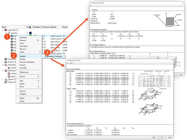
Figure 1.
Engineering Constants
- Selection of multiple entities of the same type is also supported and generates multiple tabs in the Engineering Constants result view which contain the corresponding results.
- Results can be marked with left-click (or Ctrl + left-click for multiple results) and then saved to clipboard with Ctrl + C for transfer to spreadsheet.
- Engineering constants
- 2D/3D material matrices
Calculations are output in the material system. Note that 3D properties can only be calculated for materials which provide the necessary data (for example, OptiStruct MAT9OR).
- Engineering constants
- 2D/3D material matrices
Calculations are output in the laminate’s material reference orientation. Accordingly, the ply angle entered in the ply Orientation field is used to transform the properties from ply fiber direction to the laminate material reference orientation. For more information, refer to Fiber Orientation.
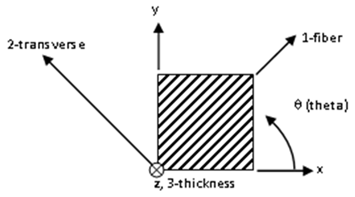
Figure 2.
- Stiffness and compliance matrices
- Homogenized engineering constants
- Normalized homogenized matrices
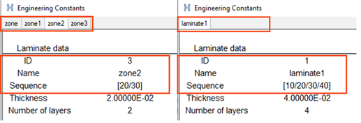
Figure 3.
- Stiffness and compliance matrices
- Homogenized engineering constants
- Normalized homogenized matrices
Additionally, stacking sequence, thickness and number of layers are summarized for each zone.
Solver Specific Details
Entities created in the Composite Browser are assigned the most common solver card for a typical ply-based model. Properties and Shapes are filtered based on solver card to only display appropriate cards for a ply-based model. Additionally, in the OptiStruct profile, the appropriate card is set for laminate and ply entities upon creation.
| Entity | Supported Cards |
|---|---|
| Laminate | STACK |
| Material | MAT1, MAT8, MAT9OR |
| Ply | PLY |
| Zone | None |
| Entity | Supported Cards |
|---|---|
| Laminate | Via property *SHELL_SECTION_COMPOSITE |
| Material | *MATERIAL, with type ISOTROPIC, ENGINEERING CONSTANTS or LAMINA |
| Ply | None |
| Zone | None |
| Entity | Supported Cards |
|---|---|
| Laminate | Via property *SHELL_SECTION_COMPOSITE |
| Material | MAT1, MAT8 |
| Ply | None |
| Zone | None |