HL-T: 2010 Welded + Unwelded Material Certification (FKM)
This tutorial guides you through a step-by-step process that covers the certification of both welds and unwelded material in the same calculation.
Note: Currently, unwelded calculations cannot by-pass the weld calculation
workflow.
Before you begin, copy the file(s) used in this tutorial to your
working directory.
- HL-2010\sidedoor_gp.hm
- HL-2010\sidedoor_gp.h3d
Import the Model and Results File
-
From the Home tools, Files tool group, click the Open Model tool.

Figure 1.The Open Model/Results Files dialog opens. -
Click Apply.
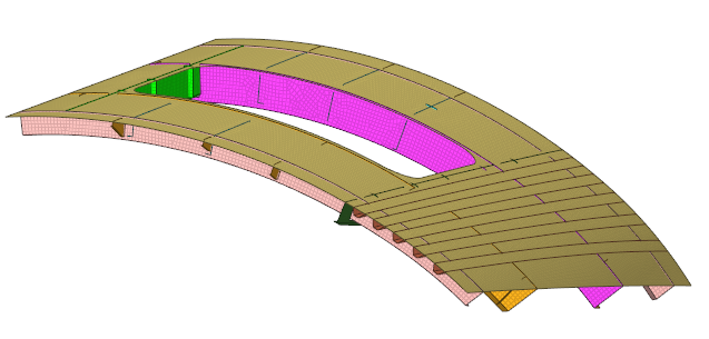
Figure 2.
Identify Weld Lines
-
Click the Mark Welds tool.
 Figure 3. The Mark Weld dialog opens.
 -
Click Detect.
HL-WC identifies the welds present in the model and highlights them in red.
Once detection is complete, a message stating the number of weld lines identified is displayed.
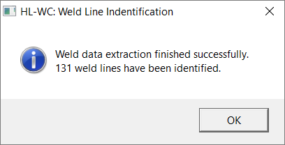
Figure 4.The weld line browser is updated.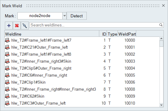
Figure 5.
Screen Welds
-
Click the Inspect tool.
 Figure 6. The Inspect Browser dialog opens.
 -
Enter a threshold value of 100.
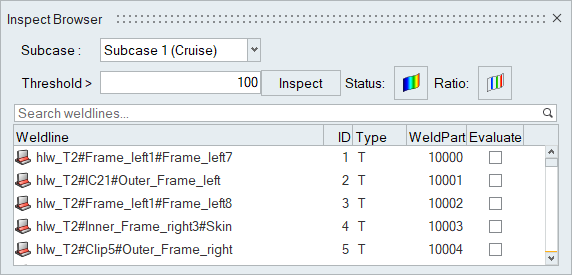
Figure 7. -
Click Inspect.
Once the screening is complete, a dialog will display the number of failed weld lines.
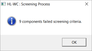
Figure 8. -
Click OK.
The legend on the right side of the modeling window colors failed weld lines in pink.
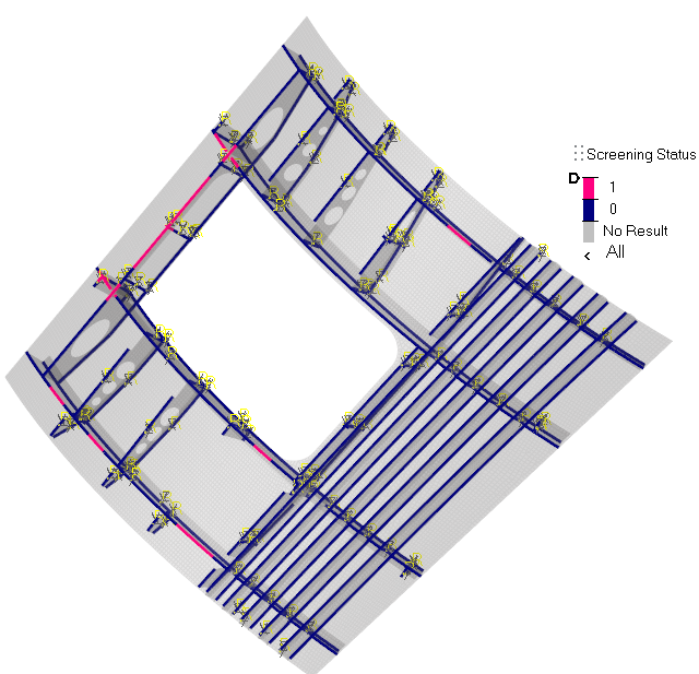
Figure 9. - Optional:
Click
 in the
dialog to plot the ratio of the von Mises stress value of an element and the
threshold value you provided.
in the
dialog to plot the ratio of the von Mises stress value of an element and the
threshold value you provided.
Define a Weld Specification
-
Click the Specifications tool.
 Figure 10. The Weld Specification dialog opens.
Review Evaluation Points
-
Click the Points tool.

Figure 11.The Evaluation Points dialog opens. -
Review the classification parameters.
The classification parameters for each weld vary depending on the weld type and the weld regulation selected.
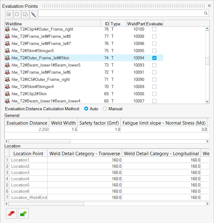
Figure 12.
Create and Assign a Material
-
Click the Material tool.

Figure 13.The Assign Material dialog opens. -
Click
 to select all the
parts.
to select all the
parts.
-
Click
 .
A new material named Material2 is created.
.
A new material named Material2 is created. -
Modify the material parameters.
- Set the Tensile Strength to 690.
- Set the Yield Strength to 360.
- Set the Normal Fatigue Limit to 310
- Set the Shear Fatigue Limit to 180.
- Accept all other default parameters and click Plot & Save.
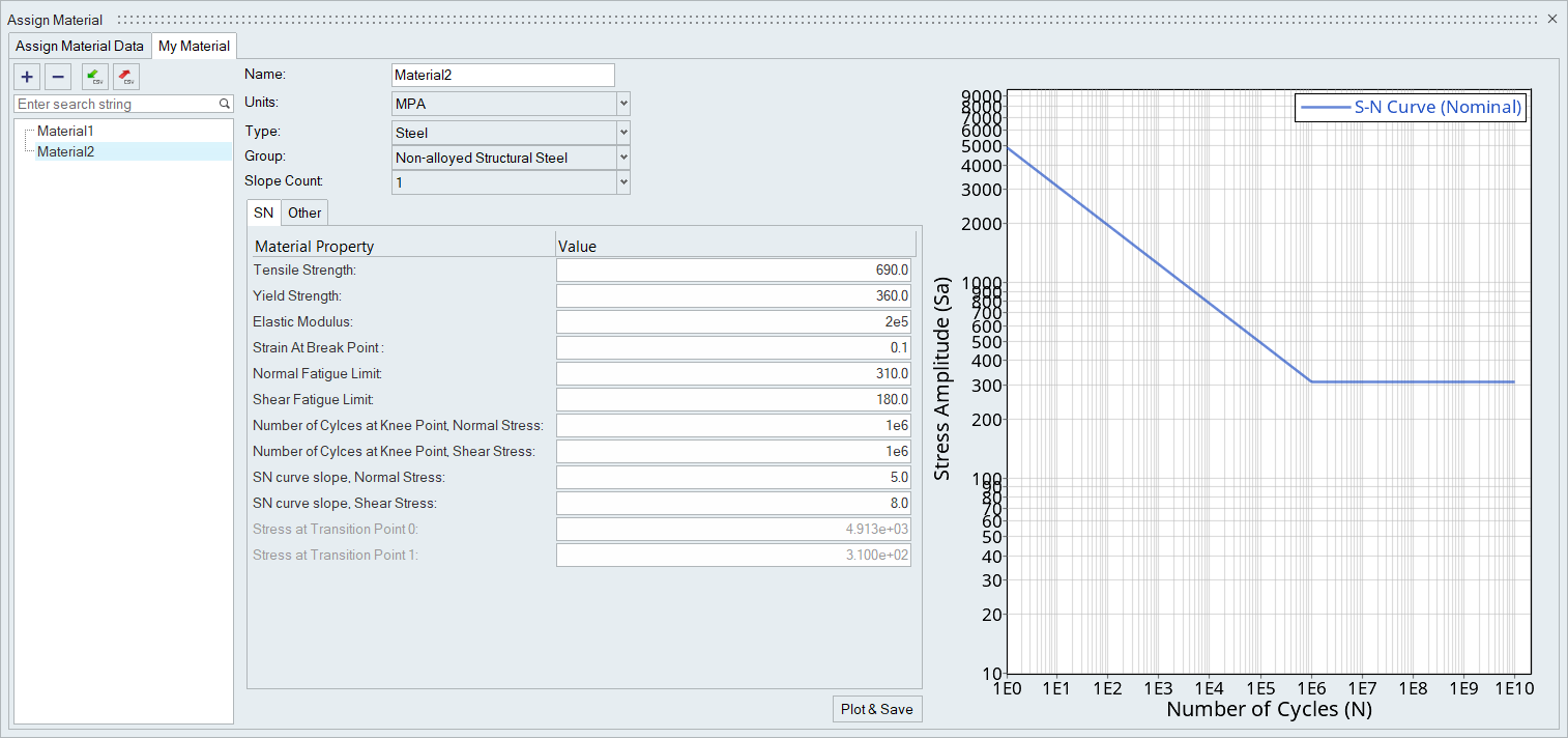
Figure 14. -
Accept the default materials and parameters for all other parts.
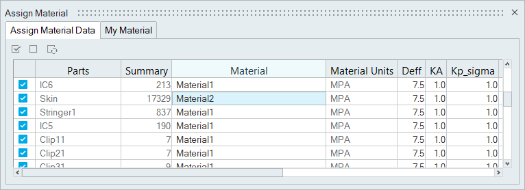
Figure 15.
Evaluate and View Results
-
From the Evaluate tool group, click the
Run Analysis tool.
 Figure 16. The Evaluate Welds dialog opens.
 -
Select Both Welds and Unwelded for the evaluation
domain.
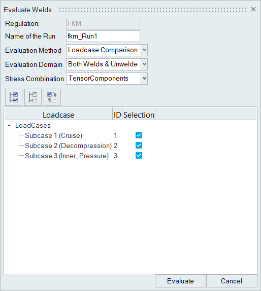
Figure 17. -
Click Evaluate.
Both the welds and unwelded elements are evaluated.
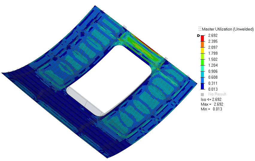
Figure 18.By default, Max Utilization - Unwelded is contoured.
-
In the Results Explorer, select Top
Layer and Utilization_X from the contour
result drop-down menus and click
 .
The selected result type is contoured.
.
The selected result type is contoured.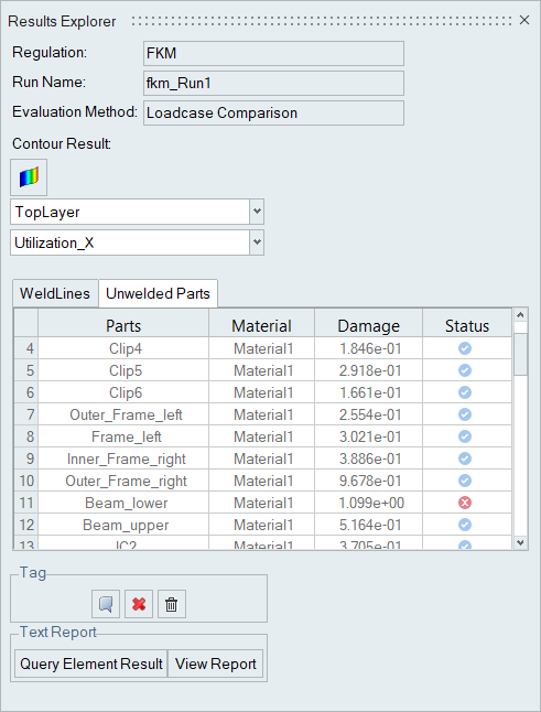
Figure 19. -
Add tags to elements.
-
Under the Tag field of the Results Explorer,
click
 .
.
-
Click
 on the
entity selector.
The selected elements are tagged with IDs and utilization values.
on the
entity selector.
The selected elements are tagged with IDs and utilization values.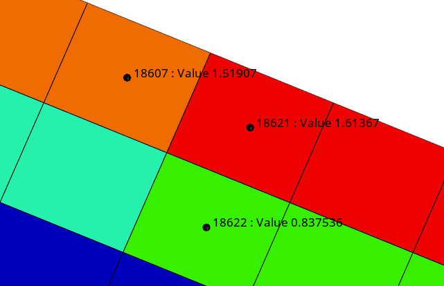
Figure 20.
-
Under the Tag field of the Results Explorer,
click