Spot Weld Fatigue Analysis
Allows for the study of fatigue performance of spot welds in structures.

Figure 1. Spot Weld Fatigue
The length of the spot weld is determined by the attached shell thicknesses. If T1 and T2 are the thicknesses of the two shells, then the length of the spot weld element, L is equal to (T1+T2)/2.
Implementation
The simplified representation of a spot weld is used in HyperLife to model the fatigue behavior at the weld.
A single weldment may contain a number of sections welded together with welds of different types. However, in this section you only look at analyzing the sections that contain spot welds. Refer to Seam Weld Fatigue Analysis for details about other weld types.
Simplified Spot Weld Representation
A spot weld is represented as a CBAR, CBEAM, CWELD, or CHEXA elements connected to two sheets of shell elements (PSHELL). The CWELD and CBEAM elements are equivalent to a CBAR element internally. The CHEXA element grid point forces are resolved as beam forces at the geometric centers of each face and then they are considered similar to other 1D elements for fatigue calculations.
Spot Weld Fatigue

Figure 2. Spot Weld Fatigue Locations
The following sections illustrates how stresses and subsequently damage are calculated at each of the three locations shown in Figure 3.
Sheet Location (1 or 2)
At sheet location 1 or 2, damage is calculated at the point where the weld is attached to the sheet/shell.
The sheet location 1 is identified by the end A (grid GA) of the nugget (for 1D element nugget) and the face corresponding to the lowest ID’s of the nugget (for CHEXA element nugget). For the structure of CHEXA nugget, refer to Fatigue Input/Output.
The sheet location 2 is identified by the end B (grid GB) of the nugget (for 1D element nugget) and the face corresponding to the highest ID’s of the nugget (for CHEXA element nugget). For the structure of CHEXA nugget, refer to Fatigue Input/Output.

Figure 3. Forces and Moments of Interest at the Sheet Locations
for
- Diameter of the weld element
- Thickness of the sheet under consideration for damage calculation
- Calculated as
The equivalent radial stresses are calculated at intervals of (Default =18 degrees). The value of can be modified by varying the NANGLE field in the Assign Material tool. Subsequently, Rainflow cycle counting is used to calculate fatigue life and damage at each angle (). The worst damage value is then picked for output. A similar approach is conducted for the other sheet.
Nugget Location

Figure 4. Forces and Moments of Interest at the Nugget Cross-Section
for
is the diameter of the weld element.
is the thickness of the sheet under consideration for damage calculation.
The stresses are calculated at intervals of (Default =18 degrees). The value of can be modified by varying the NANGLE field in the Assign Material tool. The equivalent maximum absolute principal stresses are calculated for each from and . These stresses are used for subsequent fatigue analysis. Rainflow cycle counting is used to calculate fatigue life and damage at each angle (). The worst damage value is then picked for output. A similar approach is conducted for the other sheet.
Fatigue Input/Output
Fatigue input for Spot Weld Fatigue Analysis can be divided into the following categories:
Fatigue Element Identification
- The spot welds (CBAR, CWELD, CBEAM) are referenced with the connected sheets as groups. These groups are currently referenced through components.
- The spot weld diameter, which is a function of the minimum shell element thickness, should be input in the Assign Material dialog.
- The result file should contain the shell thickness output to be automatically referred to the HyperLife Assign Material tool.
- CHEXA elements
can be used to define the weld element for Spot
Weld Fatigue Analysis. In such cases, the grid
point forces are resolved into corresponding
forces and moments at the face centers of the
opposing faces connected to the shells. The faces
of the CHEXA element attached
to the sheets should always consist of grid points
in the following order.

Figure 5. Faces of the CHEXA that Should be Used as Connection Faces with Shells for Spot Weld Fatigue
Additionally, the default weld element diameter of the CHEXA element for spot weld fatigue is equal to two times the smallest distance from the attachment face centroid to the edges.
Fatigue Parameters (Spot Weld Fatigue Dialog)
Figure 6.
- The RUPP method is currently applied to calculate the spot weld fatigue analysis.
- The spot weld fatigue parameters are applied in this dialog.
- Mean stress and thickness corrections
are to be activated if the corresponding
parameters are to be applied in the Assign
Material dialog.
For more information on FKM mean stress correction, see the FKM section under Uniaxial S-N Fatigue.
- FE Model units are specified in this
dialog. The default unit specified is MPa.
Thickness reference will be automatically modified
based in the FE model unit selection.
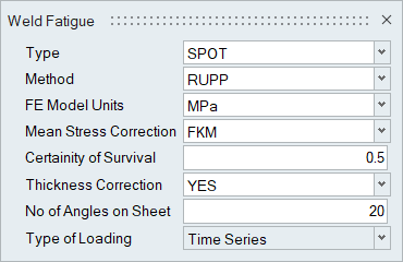
Figure 7.
Fatigue Material
- The material properties (SN curve attributes for sheet 1, sheet 2, and the nugget) to be associated with the spot weld group are specified in the Assign Material dialog (SN attributes from the My Material or Material Database tab).
- The mean stress sensitivity value and the thickness correction values are specified in the Assign Material dialog.
- By default, the shell thickness of the sheets is referenced from the model. The sheets are editable in HyperLife.
- The spot weld diameter is to be specified in the Thick/Dia entry in the Assign Material dialog.
- TREF is set to 25mm by default, which is
equivalent to 1 inch, as specified by the
standard.
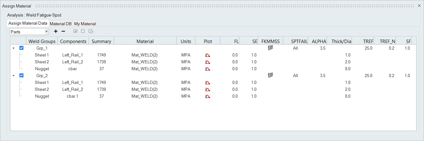
Figure 8.
- SPTFAIL
- Damage assessment option type
- ALPHA
- The value of α used to determine the AUTO option on the SPTFAIL field
- TREF
- Reference thickness for thickness effect consideration
- TREF_N
- Exponent for the thickness effect consideration
- SF
- Stress scale factor.
Fatigue Loads
- Similar to regular fatigue analysis, the fatigue loads are specified in the Load Map tool.
Output
Output for Spot Weld Fatigue Analysis is provided similar to regular Fatigue Analysis results. Damage and Life results for the SHEET, NUGGET, ALL or Auto are available based on the SPTFAIL selection in the Assign Material dialog. The damage calculation lists the worst damage if Auto is selected.