Assign Materials to Parts
Assign pre-existing or user-generated materials to the model's parts, components, and element sets.
The Assign Material dialog is dynamic and changes the list of available parameters based on the fatigue module selected.
Note: HyperLife supports only amplitude based curves, unlike
OptiStruct which supports both amplitude and
range.
-
Click the Material tool.

Figure 1.The Assign Material dialog opens.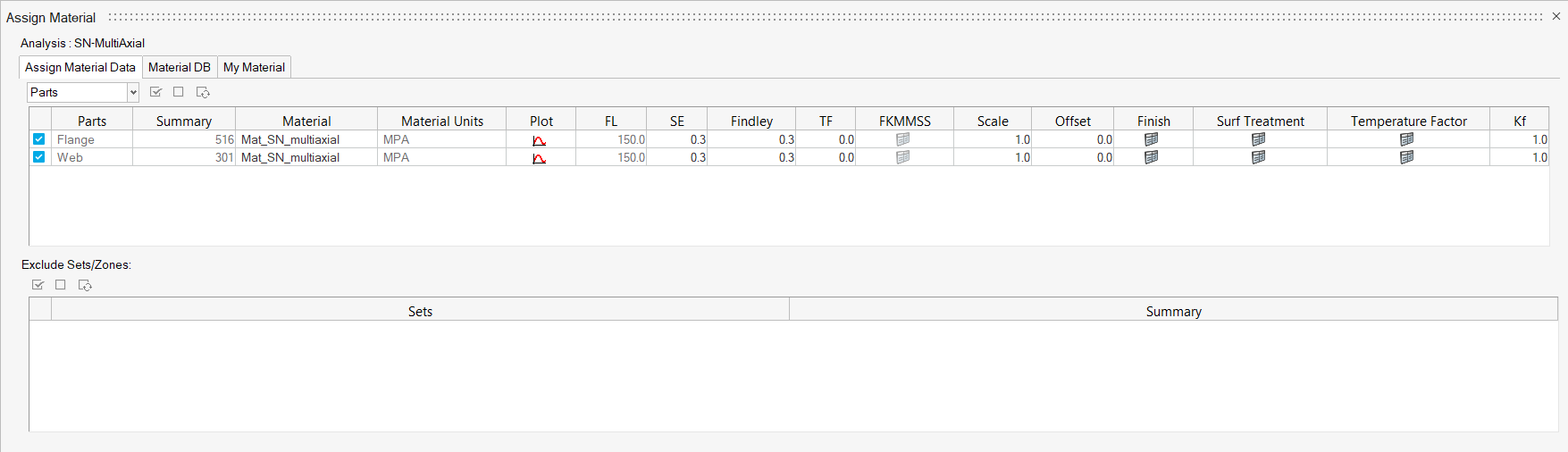
Figure 2. -
Activate the checkboxes next to the components/sets that are to be
evaluated.
Note: The Assign Material Data tab will look slightly different if you're performing a seam weld analysis. After selecting a part or a set, click Find Weld Toe, Root to find adjacent attached components. You will also notice two material, standard error, and fatigue limit categories: B and M. M stands for membrane and B stands for bending.
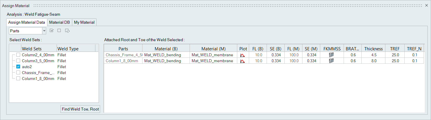
Figure 3. -
Right-click on a material and select Add to Assign Material
List.
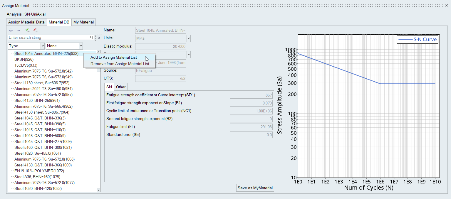
Figure 4.Note: For EN calculations, a warning is shown if there is no Poisson's Ratio available for the assigned material. Click Yes in the dialog to proceed with a default value of 0.3.
Tip:
- Use the selection icons to quickly select all, none, or reverse your selection of parts/sets.
- Click
 to display the plot curve for a material.
 - Apply a parameter's value to all the parts/sets by right-clicking on a parameter and selecting Apply current value to all Parts/Sets.