|
»Click here to display Table of Contents«
|

Cutting the Model |

|

|

|

|
|
Cutting the Model |
|
|
|

|
|
»Click here to display Table of Contents«
|
Cutting the Model |
|
|
|
|
|
Cutting the Model |
|
|
|
|
| 1. | From the Menu Bar, select Process > Submodeling. |
The Submodeling window appears.
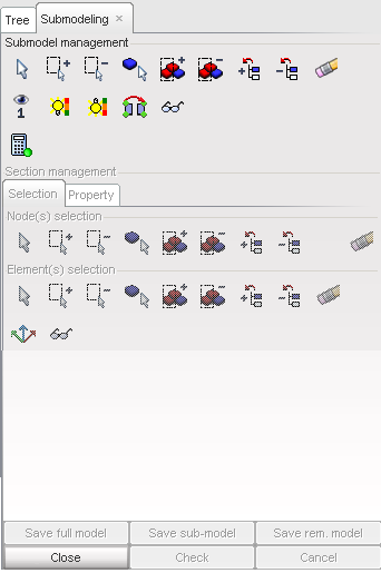
| 2. | Select faces and parts to define the submodel: |
Button |
Behavior |
|
pick elements in the graphic window. When finished, answer the question in the Dialog menu bar with Yes or Cancel. |
|
add nodes by box selection. The default box is rectangular. Use the SHIFT key to define a polygon box. |
|
remove nodes by box selection. The default box is rectangular. Use the SHIFT key to define a polygon box. |
|
pick parts in the graphic window. When finished, answer the question in the Dialog menu bar with Yes or Cancel. |
|
add parts by box selection. The default box is rectangular. Use the SHIFT key to define a polygon box. |
|
remove parts by box selection. The default box is rectangular. Use the SHIFT key to define a polygon box. |
|
add the parts selected in the tree. |
|
remove the parts selected in the tree. |
|
clear or cancel the selection. |
| 3. | Check the submodel selection: |
Button |
Behavior |
|
view only the submodel. |
|
highlight the submodel. |
|
highlight the remaining model. |
|
reverse the selection. The selected faces become the remaining model. |
|
update the display of the submodel. |
|
calculate the boundary of the submodel. |
From the Section management window, in the Selection folder:
| 1. | Add nodes to the submodel boundary: |
Button |
Behavior |
|
pick nodes in the graphic window. When finished, answer the question in the Dialog menu bar with Yes or Cancel. |
|
add nodes by box selection. The default box is rectangular. Use the SHIFT key to define a polygon box. |
|
remove the nodes by box selection. The default box is rectangular. Use the SHIFT key to define a polygon box. |
|
pick parts in the graphic window. When finished, answer the question in the Dialog menu bar with Yes or Cancel. |
|
add parts by box selection. The default box is rectangular. Use the SHIFT key to define a polygon box. |
|
remove the parts by box selection. The default box is rectangular. Use the SHIFT key to define a polygon box. |
|
add the parts selected in the tree. |
|
remove the parts selected in the tree. |
|
clear or cancel the manual selection. |
| 2. | Add elements to the submodel boundary: |
Button |
Behavior |
|
pick faces in the graphic window. When finished, answer the question in the Dialog menu bar with Yes or Cancel. |
|
add faces by box selection. The default box is rectangular. Use the SHIFT key to define a polygon box. |
|
remove the faces by box selection. The default box is rectangular. Use the SHIFT key to define a polygon box. |
|
pick parts in the graphic window. When finished, answer the question in the Dialog menu bar with Yes or Cancel. |
|
add parts by box selection. The default box is rectangular. Use the SHIFT key to define a polygon box. |
|
remove the parts by box selection. The default box is rectangular. Use the SHIFT key to define a polygon box. |
|
add the parts selected in the tree. |
|
remove the parts selected in the tree. |
|
clear or cancel the manual selection. |
|
select three nodes to create the local skew of the section. |
|
update the display of the submodel boundary. |
From the Section management window, in the Property folder:
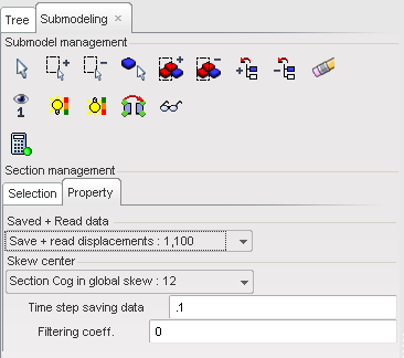
| 1. | Click Save full model to save the full model with the section force. |
| • | Select the full path and enter the file name in the Write full model window. |
| • | Select the RADIOSS format output. |
| • | Click OK to save the full model. |
| • | In the Write D01 file window, click Write D01 to save the Engine file. |
| 2. | Click Save sub-model to save the submodel. |
| • | Select the full path and enter the file name in the Write exported model window. |
| • | Enter comments in the Header of D00 window and click Save Model. |
| • | Click OK to save the submodel. |
| • | In the Write D01 file window, click Write D01 to save the Engine file. |
| 3. | Click Save rem. model to save the remaining model (optional). |
| • | Select the full path and enter the file name in the Write exported model window. |
| • | Enter comments in the Header of D00 window and click Save Model. |
| • | Click OK to save the remaining model. |
| • | In the Write D01 file window, click Write D01 to save the Engine file. |
or
| • | Click Cancel to cancel the submodeling creation. |