Points/Lines
Sketch, edit, and extrude a point, line, or polyline.
Sketch a Point or Line
Sketch a point or line.
-
Choose from the following options:
To sketch this Do this Note Point 
Click. Use snap points to create a point at a predefined point on your model such as an end, middle, center, or intersection point. Line 
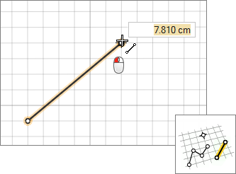
- Click twice.
- You can resize the line by entering a length.
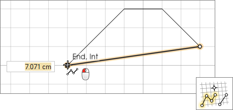
Use snap points to draw a line that is perpendicular or tangent to another line, and snap to predefined points on your model such as end, middle, center, and intersection points. Polyline 
- Click to create each point of the polyline.
- Middle-click or double-click to end the polyline.
- You can resize a line segment by entering a length.
Use snap points to draw polyline segments that are perpendicular or tangent to other lines, and snap to predefined points on your model such as end, middle, center, and intersection points.
Edit a Point or Line
Reposition, resize, or apply a sketch constraint.
First, you need to be in sketch editing mode:
- If a sketch tool is active, right-click and then mouse through the check mark to enter sketch editing mode.
- If a sketch tool isn't active, double-click a face or sketch curve.
Extrude a Sketch Curve
In push/pull mode, extrude a sketch curve into a solid.
First, you need to be in push/pull mode. You are placed into
push/pull mode automatically when you exit sketch editing mode.
Tip: Open curves that cut across the edges of a face can also be pushed and
pulled, either to create new geometry or to carve away existing material.
Keyboard Shortcuts & Mouse Controls
| To | Do this |
|---|---|
| Constrain line to one direction | Shift+drag |
| Enter sketch mode | Double-click twice on a face |
| Exit sketch mode and enter sketch editing mode | Right-click and mouse through the check mark to exit, or double-right-click. |
| Exit sketch editing mode and enter push/pull mode | Right-click and mouse through the check mark to exit, or double-right-click. |
| Exit push/pull mode | Right-click and mouse through the check mark to exit, or double-right-click. |
| Exit the tool | Right-click and mouse through the check mark to exit, or double-right-click. |