Calculating the Port Parameters and Field Data
Use the Multiport post-processing application macro in POSTFEKO to calculate the port reflections and field data for a model (plate4prt.fek) with different load configurations.
-
Specify the input method for the Multiport
post-processing
application macro.
For this example, a Feko model (plate4prt.fek) is used as input.Tip: Find the examples in the <FEKO_SHARED_HOME> directory:
%FEKO_SHARED_HOME%/installedapplicationmacrolibrary/POSTFEKO/MultiportCalculation/examples.
-
In the Model field, browse to the file location
of plate4prt.fek.
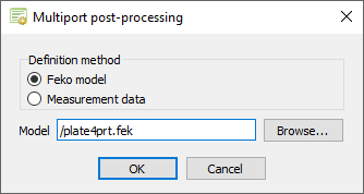
Figure 1. The Multiport post-processing dialog.
The Processing options dialog is displayed. -
In the Model field, browse to the file location
of plate4prt.fek.
-
Specify the processing options and data handling.
-
[Optional] In the Results prefix (optional)
field, specify a results prefix to group the calculated results in
POSTFEKO.
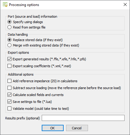
Figure 2. The Processing options dialog.
The Select ports to load dialog is displayed. -
[Optional] In the Results prefix (optional)
field, specify a results prefix to group the calculated results in
POSTFEKO.
-
Specify the non-active (terminated) ports.
For this example, only Port_3 and Port_4 are non-active (terminated) ports.
-
Under Load specification type, select
Point loads (multiple 1-port loads of varying
types) to specify the individual loads.
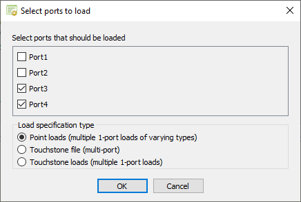
Figure 3. The Select ports to load dialog.
The Load type for terminated ports dialog is displayed. -
Under Load specification type, select
Point loads (multiple 1-port loads of varying
types) to specify the individual loads.
-
Specify the load types for the non-active (terminated) ports.
-
In the Load type for port Port_4 field, select
Complex load.
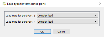
Figure 4. The Load type for terminated ports dialog.
The Select load parameters dialog is displayed. -
In the Load type for port Port_4 field, select
Complex load.
-
Specify the load values for the non-active (terminated) ports.
-
Under Port_4 (Complex impedance), specify the
following values in Ohm:
- Real component: 75
- Imaginary component: 0
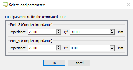
Figure 5. The Select load parameters dialog.
The Select source parameters dialog is displayed. -
Under Port_4 (Complex impedance), specify the
following values in Ohm:
-
Specify the excitations for the active ports and the load impedances.
-
Specify the excitation for Port_2.
- Under Port_2, in the Definition method drop-down list, select Direct connection.
- Specify the following values:
- Amplitude: 2 V
- Phase: 0°
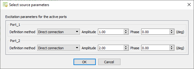
Figure 6. The Select source parameters dialog
The new results are calculated and available in POSTFEKO in the Project Browser under Stored data.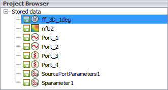
Figure 7. The multiport results under Stored data. -
Specify the excitation for Port_2.
-
[Optional] Run the plate4prt_example1_reference.cfx in
CADFEKO, load the
plate4prt_example1_reference.fek in the
plate4prt.pfs session and compare the results to the
Solver.
The field data is compared as calculated by the Multiport post-processing application macro to the solution obtained by the Solver, see Figure 8 and Figure 9.
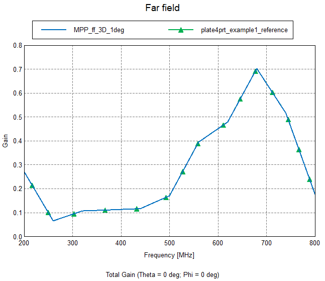
Figure 8. Comparison of near field values as a function of frequency at an arbitrary position.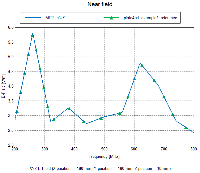
Figure 9. Comparison of far field gain over frequency in an arbitrary direction.