 icon, in the upper
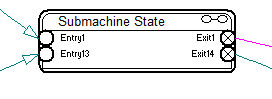
right corner of the state, distinguishes it from a simple state.
icon, in the upper
right corner of the state, distinguishes it from a simple state.To dive into the next lower level of a submachine state, double-click the Header bar.
A state chart that contains a submachine state is called the containing state chart. You can have multiple levels of containing state charts. Transitions in the containing state chart can have entry and exit points of the inserted state chart as targets and sources.
A submachine state is semantically equivalent to a composite state with a single region. The entry, exit, and behavior actions and internal transitions are defined as part of the state.
You enter a submachine state in the same way as you enter a non-orthogonal composite state. You can also enter and leave a submachine state, in contrast to an ordinary composite state, via entry and exit points.
When you open the dialog box for the submachine state block, you can adjust its size by dragging the diagonal lines in the lower left corner.
For information on editing submachine states, see Working with states and pseudo-states.
Connection Point References
When you exit a submachine state, the entry/exit point references appear on the edge of the submachine state.
Constraints
•Only submachine states can have connection point references.
•The connection point references used as destinations/sources of transitions associated with a submachine state must be defined as entry/exit points in the submachine state chart.
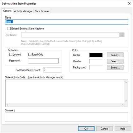
Background: Specifies the color of the decomposition region of the state.
Border: Specifies the color for the state borders.
Header: Specifies the color of the header region. To change the font color, use the View > Fonts command.
Comment: Indicates information or notes about the state. The comments only appear in the dialog box.
Embed Existing State Machine: Reserved.
Name: Specifies a name for the state. The name can be alphanumeric characters. It must be unique with respect to other state names in the state chart.
Protection: Restricts access to the submachine state. To lock the submachine state, activate Locked and enter a password in the Password box. To make the submachine read-only, activate Read-Only and enter a password in the Password box.
State Activity Code: Specifies one or more actions and associated behaviors. Enter and edit state activity code in the Activity Manager window.
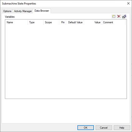
Comment: Indicates user-specified comments.
Default Value: Indicates the initial value for the variable.
Name: Indicates variable names. See Setting up state chart variables.
Pin: Indicates the input or output pin number on the state chart block. For State ID, it indicates the active state from the given region.
Scope: Indicates how the variable is scoped. See Defining variable scope.
Type: Indicates the data type of the variable. See Defining variable data types.
Value: Indicates the current value of the variable.

The submachine state State2 has one entry point and one exit point. The next lower level of State2 has two exit points.