Motivation for Different Propagation Models
For the installation of mobile radio systems, wave propagation models are necessary to determine propagation characteristics for any arbitrary configuration. The predictions are required for proper coverage planning, the determination of multipath effects as well as for interference and cell calculations, which are the basis for the high-level network planning process. In a GSM/DCS-system, this planning process includes, for example, the prediction of the received power to determine the parameter sets of the base stations. With the introduction of wireless broadband services in third generation systems (UMTS) or wireless local area networks (W-LAN) the wideband properties (for example, delay spread, angular spread, and impulse response) of the mobile radio channel are important for the planning process.
The environments where these systems are intended to be installed are ranging from indoor to large rural areas. Hence wave propagation prediction methods are required covering the whole range of macro-, micro- and pico-cells including indoor scenarios and situations in special environments such as tunnels or along highways.
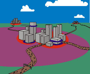
Figure 1. Environments for the definition of different cell types.
Four basic mechanisms generally describe the phenomena that influence radio wave propagation:
- reflection
- diffraction
- penetration
- scattering
In the first step, the propagation environment is digitized to create a database suitable for propagation modeling. For the prediction of macro-cells the database includes terrain height information and land usage data. For urban environments building shape, height information and building surface are taken into account. Different types of databases with various resolutions and accuracy are used according to the specified scenario. Investigations have been focused on proper techniques to consider the relevant information in a time-efficient manner. Therefore easy format descriptions are applied, and various data converters are available.
The second step is the definition of mathematical approximations for the physical propagation mechanisms. These topics are described in the sections that follow. Basic problems such as the diffraction around a non-perfectly conducting wedge, representing a building corner and the modeling of propagation over rooftops are addressed.
Based on the solutions for the basic problems both deterministic and empirical approaches have been developed and implemented for the various environments, which is the third modeling step.
In the different environments, distinctions of the propagation models are required both in terms of the dominant physical propagation phenomena and the specification of the utilized database describing the considered scenario. All models dedicated to the same environment and cell type are treated in separate sections. As the definition of cell types is not unique in literature, the cell type definition used in this documentation is explained in more detail.
In large cells and small cells the base station antenna is usually installed above the average rooftop level of the surrounding buildings. Therefore the path loss is determined mainly by diffraction at rooftops, and as a result, the main rays propagate above the buildings. Contrary to this scenario for micro cells, the base station antennas are mounted below the rooftop level of the surrounding buildings. In this case wave propagation is determined by diffraction around and reflection from buildings which could lead to wave guiding effects in street canyons. Pico cells are applied to provide indoor coverage or to cover very small outdoor areas. In any case, the base station antenna of a pico cell is mounted inside a building or well below rooftop level where outdoors. An overview of the different cell types and their description is provided in Table 1.
| Cell Type | Typical Cell Radius | Typical Position of a Base Station Antenna |
|---|---|---|
| macro cell (large cell, terrain) | 1 km to 30 km | outdoor, mounted above medium rooftop level, heights of all surrounding buildings are below base station antenna height |
| mini cell (small cell, suburban) | 0.5 km to 3 km | outdoor, mounted above medium rooftop level, heights of some surrounding buildings are below base station antenna height |
| micro cell (small cell, urban) | up to 1 km | outdoor, mounted below medium rooftop-level, heights of some surrounding buildings are above base station antenna height |
| pico cell (indoor) | up to 500 m | indoor or outdoor (mounted below rooftop level) |