Set Up a New Project
Learn how to set up a new project.
Set Up a Wave Propagation Project
To start a new wave propagation project in ProMan click .
After selecting New Project, a new dialog is launched, where you have to specify the scenario and the database to be used for the new simulation project.
You will be asked to specify the display height (z-coordinate) for the 2D display later. The selected height can be changed later via .
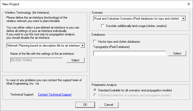
Figure 1. The New Project dialog.
- Wireless Technology
- For a pure wave propagation project select Propagation Analysis
(without network planning).Note: No network predictions are possible if Propagation only mode is selected.
- Scenario
- Selection of the environment (rural, urban, indoor, tunnel, time-variant) for the propagation project, depending on the available database.
- Databases
- Selection of the database file which shall be used for the simulations. Depending
on the chosen scenario, one or multiple database files can be specified
here.
For rural or suburban scenarios, topography and clutter databases can be either pixel or vector based databases. Vector-based topography and clutter databases are required for the rural ray-tracing model and can be selected after selecting the corresponding check box in the upper section.
Note: For simulations with the intelligent ray-tracing (IRT) wave propagation model a preprocessed database is required. This preprocessing has to be done with WallMan before the database is selected here. - Polarimetric Analysis
-
- Standard (suitable for all scenarios and propagation models)
- The antenna pattern (both for Tx and Rx) can come from a Feko
.ffe file (which
contains polarization information but the standard option will only
extract the total gain) or from other file formats such as
.apa file,
.apb file or a
.msi file (which
do not contain polarization information). When this
Standard option is used, the polarization
information is defined when antenna patterns are assigned to individual
transmitters. The selected polarization direction and cross-polarization
level (Figure 2) apply uniformly to all directions in the radiation pattern.
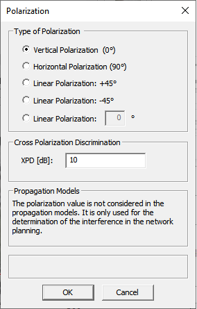
Figure 2. The Polarization dialog. - Full (limited selection of scenarios and propagation models)
-
Angle-dependent (direction-dependent) polarization information is obtained from the antenna pattern (both Tx and Rx) in the Feko .ffe file or an .ffe file created in AMan. The .ffe file contains the polarimetric information (gain and polarization) where separate patterns for theta and phi polarization are included in the file.
Due to the level of detail, this option can only be selected in conjunction with non-empirical prediction models that take the polarization accurately into account. These are standard ray tracing, intelligent ray tracing, and the multi-wall model with the use of Fresnel coefficients/UTD for transmission, reflection and diffraction. Figure 3 shows the dialog in case of an indoor scenario.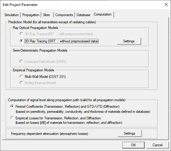
Figure 3. The Edit Project Parameter dialog - Computation tab. Available prediction models (scenario dependent) and selection of Fresnel/UTD for the full polarimetric analysis.
Configuration of a Propagation Project
- Simulation tab
- The simulation area can be changed here by editing the lower-left and upper-right corner coordinates. By default, the full area of the database will be predicted. The resolution grid of the result matrix as well as the heights of horizontal prediction planes can be changed (only if the database was not preprocessed in area mode).
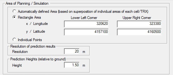
Figure 4. The Area of Planning / Simulation tab of the Edit Project Parameter dialog.
- Propagation tab
- On this tab, you have to specify a directory where the computed propagation results shall be saved. Besides this, all simulation results which can be computed with the selected wave propagation model are listed here. You can select available result types by selecting the related check box.
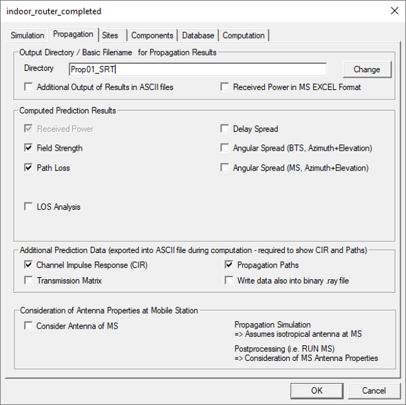
Figure 5. The Propagation tab of the Edit Project Parameter dialog.
- Database tab
- No changes are required here, as the databases have been loaded during setup of the network project.
- Computation tab
- The wave propagation model and the settings have to be specified on the Computation tab.
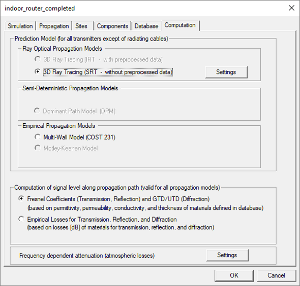
Figure 6. The Computation tab of the Edit Project Parameter dialog.
After the configuration of the project (including definition of sites / transmitters), the simulation process can be started by selecting either Propagation: Compute All from the Computation menu or the corresponding toolbar icon. Besides the computation of all transmitters, it is also possible to compute only selected transmitters or transmitters which have been modified during the planning process by selecting the corresponding menu item form the Computation menu.