Run Analysis
Define parameters and execute an analysis of a foaming part design. Generate results for individual or combined events.
Complete the model setup before running an analysis.
Tip: Analysis results
are saved in the folder specified in your Preferences settings under .
-
Click Run Analysis on the Analyze
icon.

-
Define parameters on the Preferences and Customized Results tabs of the Run
Analysis dialog.
-
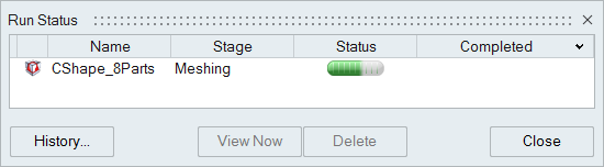
Click Run.
The run status is displayed.
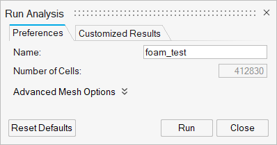
Preferences
Use the Preferences tab on the Run Analysis dialog to define the run and advanced-mesh parameters for your analysis.
Preferences Tab: Run Options
| Option | Description |
|---|---|
| Name | Type the name of the run. By default, the name of the model is used. |
| Number of Cells | This value reflects the number of cells in the voxel mesh. The value is based on the defined Uniform size of cells or Variable size of cells. Lower numbers reduce run time. Higher numbers increase accuracy. |
| Reset Defaults | Define the mesh with the default values. |
| Run | Launch the simulation. |
| Close | Close the dialog. |
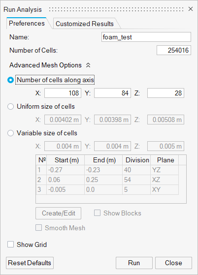
Preferences Tab: Advanced Mesh Options
Click the chevron ![]() to show the Advanced Mesh Options.
to show the Advanced Mesh Options.
| Option | Description |
|---|---|
| Number of cells along axis | Select this mesh option to produce a 3D matrix of voxel cells. Enter the number of cells along the X, Y and Z-axes. |
| Uniform size of cells | Select this option to create a mesh with uniform cells. Enter the size of cells along the X, Y and Z-axes. |
| Variable size of cells | Select this option to create a mesh-refinement zone for a
particular region of the part. Enter the size of cells along the
X, Y and Z-axes. Enter the zone parameters in the table. Apply
settings and define parameters specific to this option:
|
| Show Grid | Select this option to display the grid for the entire part. |
Customized Results
Use the Customized Results tab on the Run Analysis dialog to define specimens, sensors and output intervals for your analysis.
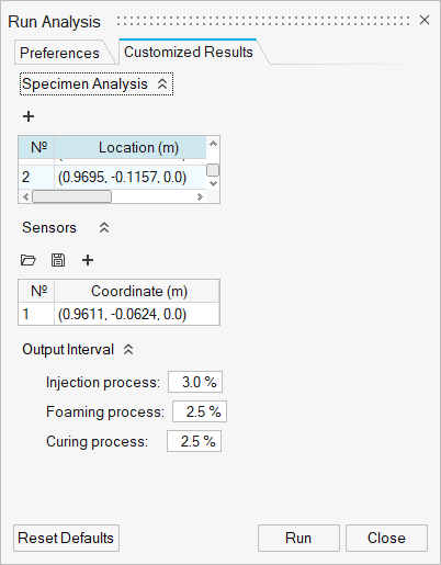
Customized Results Tab: Specimen Analysis Options
Click the chevron ![]() to show the Specimen Analysis options.
to show the Specimen Analysis options.
| Option | Description |
|---|---|
| Specimen Analysis | The Specimen options let you define a zone of particular interest on the part or mold from which analysis results can be generated. |
 |
|
Customized Results Tab: Sensors Options
Click the chevron ![]() to show the Sensors options.
to show the Sensors options.
| Option | Description |
|---|---|
| Sensors | Place sensors on your model from which results can be generated for specific locations on the model. |
 |
Select the Import button to open an existing sensor definition from a .csv or .txt file and apply it to your current model. |
 |
Select the Export button to save defined sensors to a .csv or .txt file. |
 |
Select the Plus button to create a new sensor. Drag the arrows to position the sensor or enter coordinates in the microdialog. |
Customized Results Tab: Output Interval Options
Click the chevron ![]() to show the Output Interval options.
to show the Output Interval options.
| Option | Description |
|---|---|
| Injection process | Set the output interval to be written when the injection process reaches the defined percentage of completion. |
| Foaming process | Set the output interval to be written when the foaming process reaches the defined percentage of completion. |
| Curing process | Set the output interval to be written when the curing process reaches the defined percentage of completion. |