Radome Definition
Having defined the geometric model, the radome must be created and assigned. To do that, click on Source – Radome – Define Radome menu and the Radome panel is open on right side of screen.
In the Radome panel, no radomes are created so click on Add Radome button to insert a new radome. Then, the table of interfaces of the selected radome (1) is loaded below. As we have shown in Figure 1, the radome is made of 4 interfaces that define the 3 layers, so click on New Interface button twice to get the 4 interfaces.
Each nose must be assigned to every radome interface in the same order than specified in Figure 1. Remember that the normal vectors of every interface must be pointing to the next one. To assign a nose to an interface, select the geometrical object from the tree or in the Geometry panel, then select the corresponding row in the Interfaces table, and click on Set Objects button. Then, assign the Material to its interface, which is defined to the current layer.
The material (or layers) is considered between one interface and its next one, so the last interface does not required a material.
Remember clicking on Save button to confirm the radome definition.
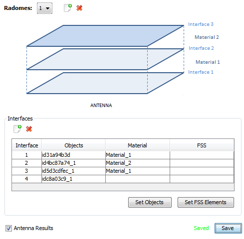
Figure 1. 27 Radome definition.
The next figure shows the final design of the radome with the horn, with the Material Lines view. In this representation, we verify that the layers of the radome have the correct materials.
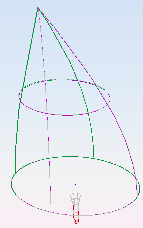
Figure 2. 28 Lines view with materials of the final design.