Passive Antenna
With this option, the user can enable the coupling effect between antennas to obtain results of this kind. Selecting Output - Passive Antenna and the following panel will be displayed to configure the passive antenna parameters.
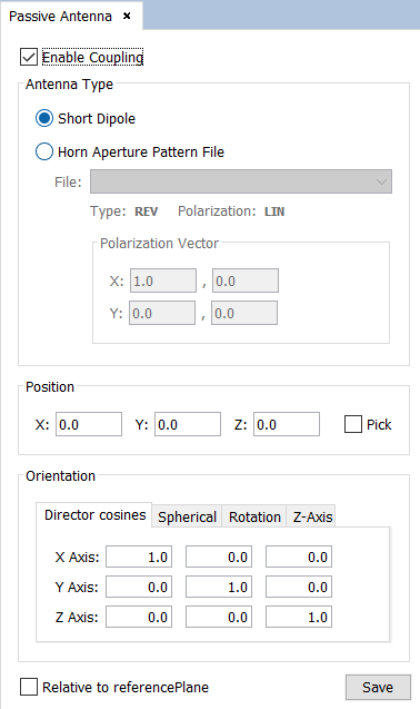
Figure 1. Passive Antenna Panel
The following parameters may be edited:
- Enable / Disable Coupling the check box on the top of the window can be enabled or disabled. This option allows computing the mutual coupling between active and passive antennas.
- Antenna Type the passive antenna can be:
- Short dipole creates a logical dipole with default length.
- Radiation pattern file. The format of the radiation pattern file can be REV, RV2 or 3DE, and the polarization can be linear ( LIN) or circular ( CIR). The name of the pattern file has to be indicated. See DIA Files to read further information regarding the DIA Files.
- Position-Coords location of the passive antenna (from the keyboard or using the mouse with ' Pick Point Edition' option).
- Polarization Vector polarization given by its real and imaginary parts for each coordinate.
- Orientation Director Cosines orientation of the passive antenna coordinate system related to the absolute coordinate system.
If all the information is correct, the antenna will be shown on the screen. A red parabola represents the active antenna and a magenta parabola the passive antenna. The axis of the antenna is also visualized. If the antenna is not visualized on the screen after pressing Save button, the most common reason is that the radiation pattern has not been found in the newFASANT installation folder.