Video: Creating a Hot Runner System
Learn how to define a hot runner system.
-
Click Open Model on the Files icon and browse to the
bumper.imold file in the installation directory, or
drag-and-drop the file into the modeling window.

-
On the Part Cavity icon, click Auto Configure
Components.

-
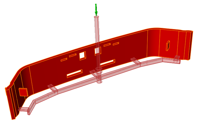
Click the surface of the inlet to automatically detect the mold part cavities
and the runner system components.
The mold part cavities are displayed in dark red and the runner system components in light red. The selected inlet has a green arrow.
-
Select the Hot Runner icon.

Use the options in the microdialog to define the hot runner system. -
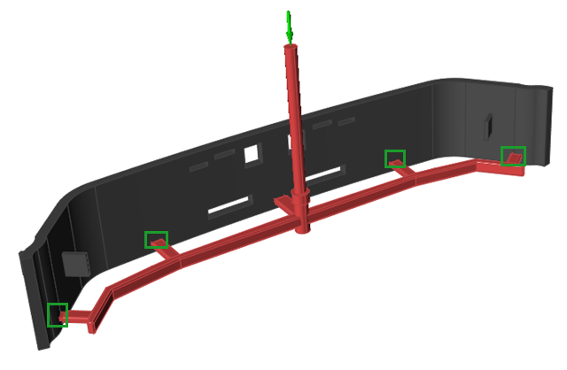
For each valve gate that you want to designate in your model, select the gate,
then define the heat controls in the microdialog. For this tutorial, you will
select and define the 4 gates outlined in green.
-
Click the point icon
 ,
then click the model where you want to place the flow front control
point.
From the valve's initial closed state, the valve will open when the material flow reaches the specified point on the model.
,
then click the model where you want to place the flow front control
point.
From the valve's initial closed state, the valve will open when the material flow reaches the specified point on the model.
-
Click the point icon