Air Nozzle Quench Zone
An air nozzle quench zone is a rectangular quench zone and has four sides: left, right, top, and bottom.
Each side of a rectangular quench zone can have a nozzle set, which can be enabled/disabled for a specific run. By default the top nozzle set is enabled. Every rectangular duct is treated as a nozzle.
-
From the Quenching ribbon, click the
Quench tool.

The secondary toolbar with quench zone types is displayed.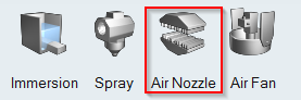
-
Click the Air Nozzle icon.
Adjust the zone position over the profile using the move tool
 in
the micro dialog to move the box in X,Y, Z directions.Clicking the
in
the micro dialog to move the box in X,Y, Z directions.Clicking the


 buttons in the
microdialog enables/disables the nozzles in the top, bottom, right or left of
the zone respectively. A rectangular air nozzle zone will be created. Microdialogs to edit the box dimensions will be populated along the width, length, and height of the box. Another microdialog with zone parameters will be populated.
buttons in the
microdialog enables/disables the nozzles in the top, bottom, right or left of
the zone respectively. A rectangular air nozzle zone will be created. Microdialogs to edit the box dimensions will be populated along the width, length, and height of the box. Another microdialog with zone parameters will be populated.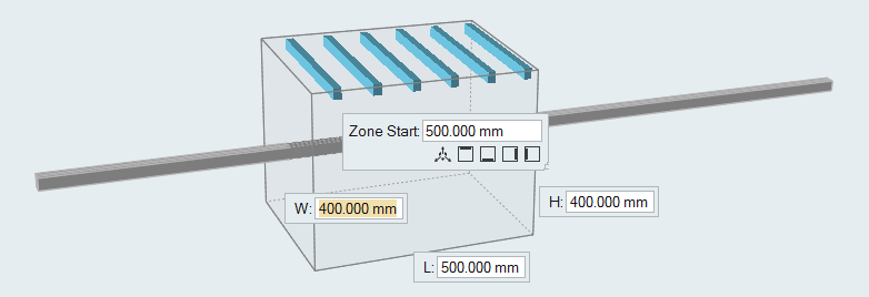
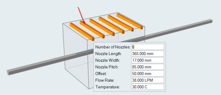
- Optional:
Change the parameters of the air nozzle by clicking the air nozzle. In the microdialog, edit the parameters and press Enter.
The air nozzles will be recreated with the new values. Nozzle Pitch is the distance between two nozzles. The position of the first nozzle is specified from the starting edge of the zone using the Start Offset value. The flow rate specified is for the entire side and is equally divided to each nozzle. Nozzles are positioned at equal distances on the side, with the specified end offset (both ends). The nozzles are perpendicular to the Z axis. Temperature of air is also specified in this dialog.