Tutorial: Optimizing a Part with Motion
Learn how to optimize a part using motion analysis results.
In this lesson you will learn how to:
- Ground a part
- Create rigid groups
- Add joints and an angle motor
- Run both transient and statics motion analyses
- Apply shape controls and symmetry
- Optimize a part using motion analysis results
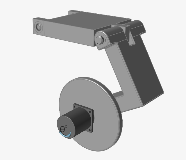
Open the CAD model
-
Double-click the M04_YBracket.x_t file in the Motion
folder to load it in the modeling window.
Ground a Part
-
Select the Ground tool from the Connections group.

-
Select the Shaft part to ground it.
The part turns red, indicating it is a ground part.
Create Rigid Groups
-
Select the Rigid Groups tool.

The selected parts turn red. -
Click the floating Create New Group button to place the
parts you selected into a new group.
-
Click Create New Group to create another rigid group that contains the Bracket
and Boss parts.
Connect Parts together with Joints
-
Select the Joints tool.

The guide bar appears with default settings (All, Auto).
-
Click the
 button on the guide bar.
Notice that four joints were created, two pin joints between moving parts in the model, and two cylindrical joints where the Y-Bracket is connected to ground.
button on the guide bar.
Notice that four joints were created, two pin joints between moving parts in the model, and two cylindrical joints where the Y-Bracket is connected to ground.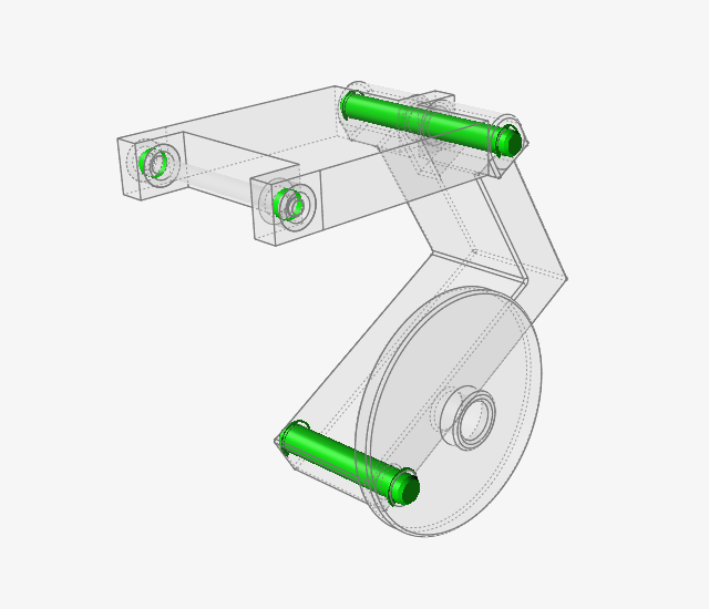
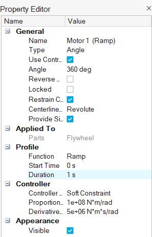
Add an Angle Motor to Control Part Angles
-
Select the Motors tool.

-
For the first connection, click the inside hole of the boss on the
Flywheel.
The selected hole feature turns red. This is the shaft connection point.
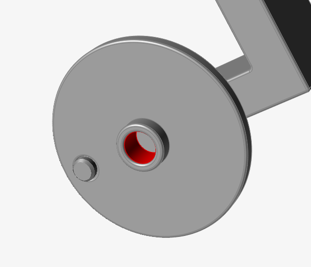
-
Click on the hole a second time.
This makes the base connection for the motor react against ground. A motor appears and the microdialog has the default setting of being a speed motor.
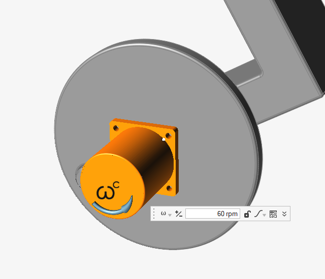
-
In the microdialog, change the motor Type from Speed to
Angle. (This is required for running a statics
analysis, which you will do later in this tutorial.)

-
Under the Profile category for Motor 1, change the
Duration to 1 s.
Set the Gravity Direction
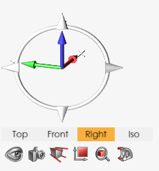
-
Select the Right view in the view controls to view the
model from the side.
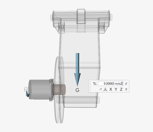
-
Select the Gravity tool.

-
Notice that a vector is displayed in the modeling window which indicates the
direction of gravity.
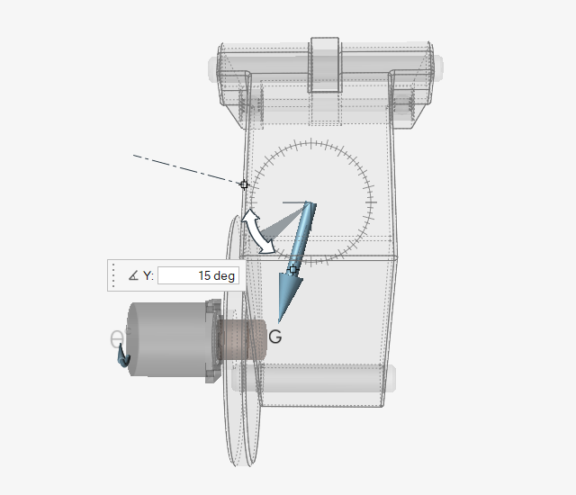
-
Reorient the gravity vector by clicking and dragging the rotator or by entering
15 deg in the microdialog to tilt the vector towards
the Flywheel, as shown:
Run a Motion Analysis to View the Mechanism's Behavior
-
Position the model as shown.
-
Click the Quick Run button on the Analyze Motion icon to
see the model in motion.

Notice that the ground parts remain stationary and the other parts move as they are being driven by the motor.
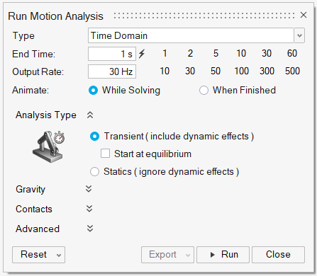
Change the Analysis Type to Statics and Rerun the Analysis
-
Hover over the Analyze Motion tool, then click the
Run Settings icon to open the Run Motion Analysis
window.

-
Change the End Time to 1 s and
select the Statics option.
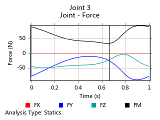
Review the Motion Analysis Results
-
Change the Time on the animation toolbar to
0.70 s by entering a value in the field or by
dragging the slider bar.

-
Select Joint 3 in the Model Browser to plot the joint
force results.
Notice that the loading in the cylindrical joint changes as the mechanism operates.
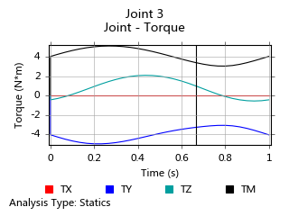
-
Right-click on the plot and select Torque.
Notice that you also see some variation in the torques as the angle of the Y-Bracket changes with respect to gravity.
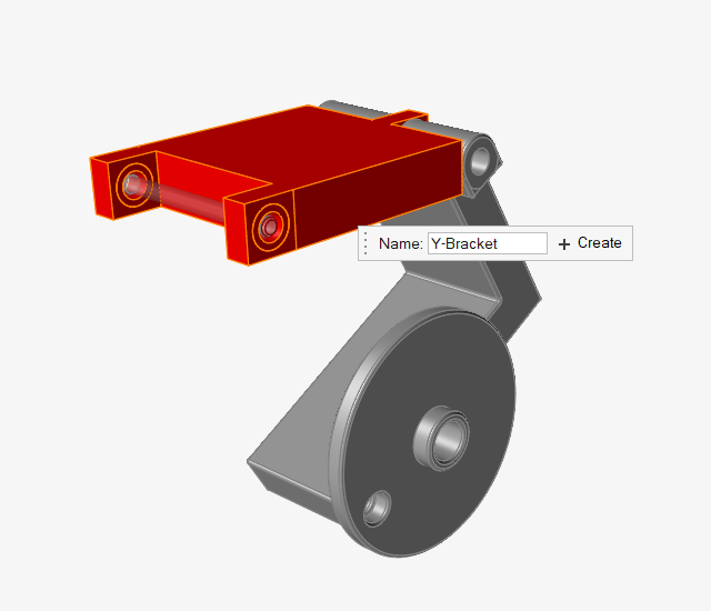
Define the Design Space
-
Right-click on the Bracket part to open the context
menu, and select Design Space.
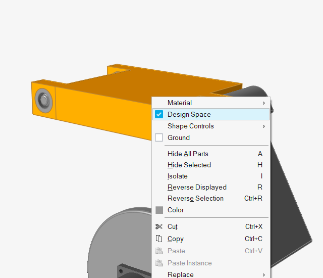
-
Click on empty space to deselect the Bracket part.
Notice its color has changed to reddish brown, indicating that it is a design space. The boss parts remain gray in color since they are considered non-design spaces.
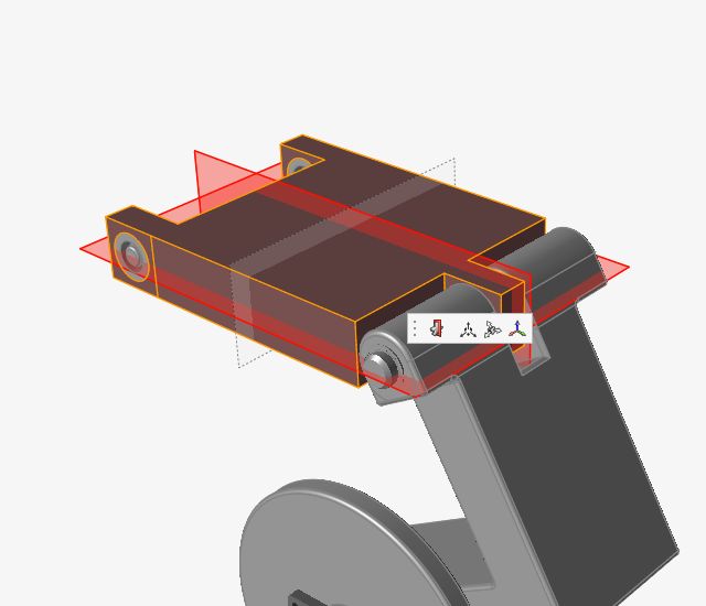
Apply Symmetry and Shape Controls to the Design Space
-
Select the Apply Symmetric Controls button from the
Shape Controls tool.

-
Make sure the Symmetric tool is selected on the
secondary ribbon.

-
Click on the symmetry plane aligned with Global XZ plane to disable it.
The plane appears transparent, as shown.
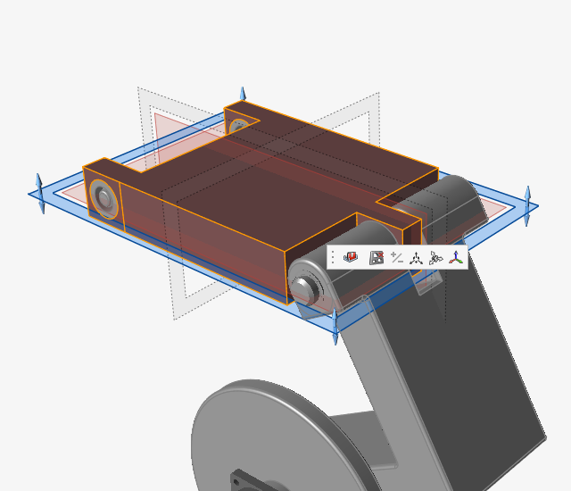
-
Select the Apply Draw Directions button from the Shape
Controls tool.

-
Choose the Split Draw option from the secondary
ribbon.

-
Select the Bracket design space.
The default draw direction plane appears as shown.
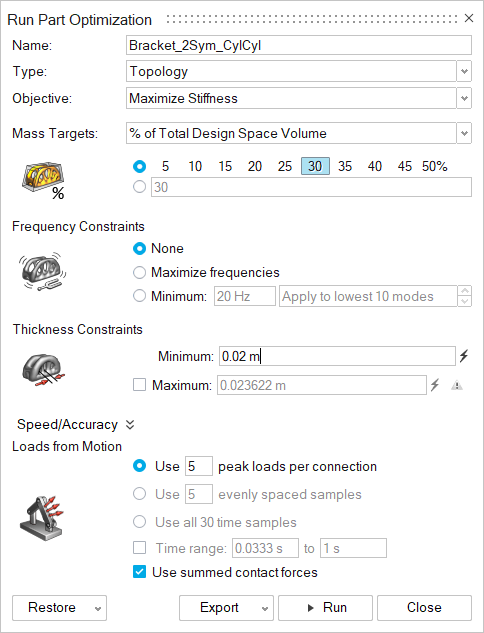
Running an Optimization
To run an optimization, open the Run Optimization window, select a run type and objective, and click Run.
Before optimizing a part, run a static motion analysis.
(Note that transient analyses are also supported for optimization, but in this tutorial
we are going to ignore dynamic effects and just use the static solution.)
-
Click the Quick Run button on the Analyze Motion tool
and let the model run to completion to generate the baseline motion analysis
results that will be used for part optimization.
-
Click Run Optimization
 on the Optimize Part icon. The bracket is
automatically selected as it is the only design space available to
optimize.
on the Optimize Part icon. The bracket is
automatically selected as it is the only design space available to
optimize.
-
Change the Name in the Run Optimization window to
Bracket_2Sym_CylCyl to indicate that you will be
optimizing the part based on having two cylindrical joints for the connections
to ground.
-
Double-click on the name of the run in the Run Status window. (Alternatively,
you can open the M04_YBracket_run.stmod file to view the results). The optimized
shape is displayed.
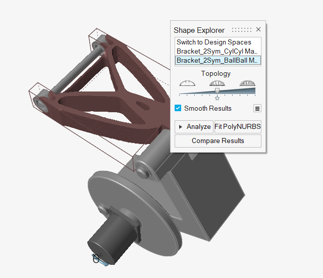
Note: If you had run the model with the default minimum thickness of .011811 m, the result would have been smoother but taken significantly longer to run. -
Select Switch to Design Spaces in the Shape Explorer to
view the original design space.
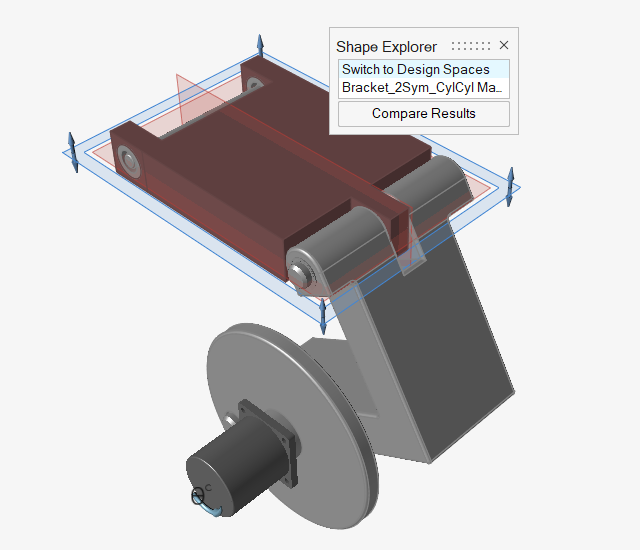
Note: If you opened the .stmod file with the run results, click the Show Optimization Results tool on the Optimized Part icon to open the Shape Explorer.
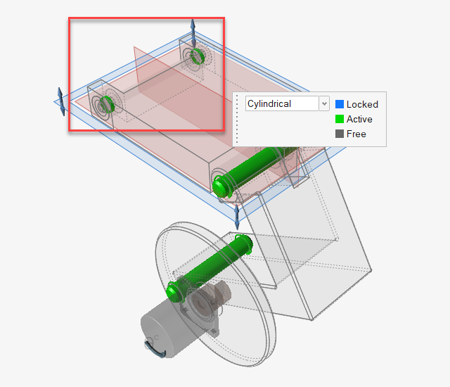
Change the Joint Type for Connections to Ground
-
Select the Joints tool.
-
Box select the two cylindrical joints from the graphics window, or multi-select
them in the Model Browser by using the Ctrl key.
Rerun the Part Optimization
-
Click Run Optimization on the Optimize Part icon.
-
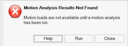
Notice this time an alert box appears.
This lets you know that because you made changes to the joint connections, you will need to run a motion analysis for the current model before you can optimize a design space.
-
Click Run Optimization on the Optimize Part icon
again.
-
Double-click on the name of the run in the Run Status window (or open the
M04_YBracket_run.stmod file from the Demo Browser to
view the results).
The new optimized shape is displayed.