OS-E: 0840 Lattice Structure Optimization
Lattice optimization of a statically loaded cantilever beam is demonstrated.
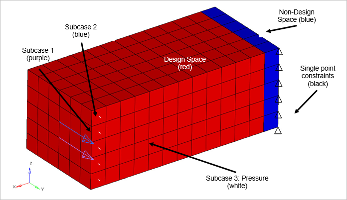
Figure 1. Cantilever Beam Finite Element Model
Model Files
Refer to Access the Model Files to download the required model file(s).
The model file used in this example includes:
lattice.fem
Model Description
The cantilever beam undergoes three separate static loadings (subcases) at its free end. illustrates their specific location, direction and magnitude.
The optimization D.R.C.O setup for this model entails creating a design variable (D) associated to the design space property. Volume fraction and weighted compliance responses (R) are created to monitor the output of the structure during each subcase. An upper bound constraint (C) of 20% is placed on the volume fraction response. Lastly, a minimize objective (O) is associated with the weighted compliance response (maximize stiffness).
- FE Model
- Cantilever Beam
- CHEXA
- MAT1
- Young’s Modulus
- 210,000
- Poisson's Ratio
- 0.3
- Density (Rho)
- 7.85e-9
- PSOLID
- Non-design space (blue)
Results
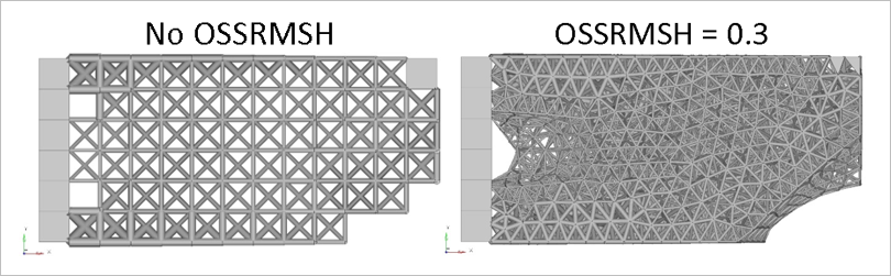
Figure 2. Comparison of OSSRMSH on the Lattice Structure
Phase 2 setup file (“_lattice.fem”) contains the converted model (solids to beams) and the necessary sizing optimization parameters; one may note how much larger and more complicated the setup has become. An equal quantity of design variables has been created as there are nodes. For each beam two design variable relationships are created – one for each end – to allow tapering. The stress constraint, and additional lattice parameters (buckling), are now applied to the beams response, and the objective has been set to minimizing the volume. The larger number of responses results in a much longer solve time.
The final .fem file contains the optimized beam properties with DIM1 and DIM1A containing the diameters of each end. Comparing the stress results of the model at iteration 0 (unoptimzed) to the final iteration (optimized) shows how localized stresses are removed and the stress constraint is satisfied.