Problem 5: Dynamic Analysis of Linkages in a Mechanism
Objective
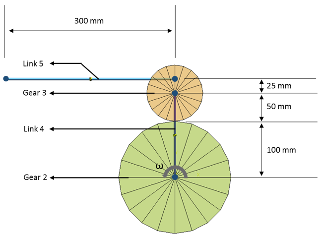
For the mechanism shown in the image below, the input gear 2 is rotating with a
constant angular velocity of 10 rad/s counter clock wise. The objective is to
determine the angular velocity of gear 3 and link 4, when the angular velocity of
link 5 is zero. Figure 1.
Entities Validated
Rigid body
Gear joint
Type of Analysis
Dynamic
Reference
THEORY OF MACHINES AND MECHANISMS, Third Edition by John J. Dicker, Jr., Gordon
R. Pennock, Joseph E. Shigley:110
Model Files
gear_joint_mechanism.mdl - MotionView Model
gear_joint_mechanism.xml - MotionSolve Deck
Graphical Results
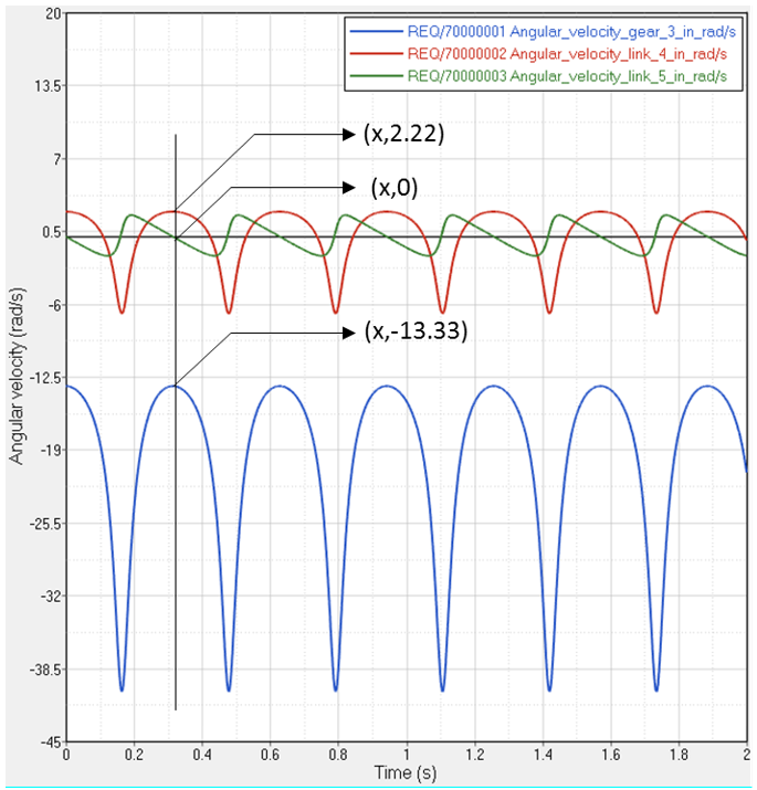
Figure 2.
Result Comparison
Output
Analytical
MotionSolve
% Error
Angular velocity of gear 3 (rad/s)
-13.33
-13.33
0%
Angular velocity of link 4 (rad/s)
2.22
2.22
0%
Conclusion
MotionSolve results compare well with analytical results.