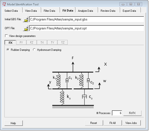
If your project uses a rubber bushing, then the following page
appears: Figure 1.
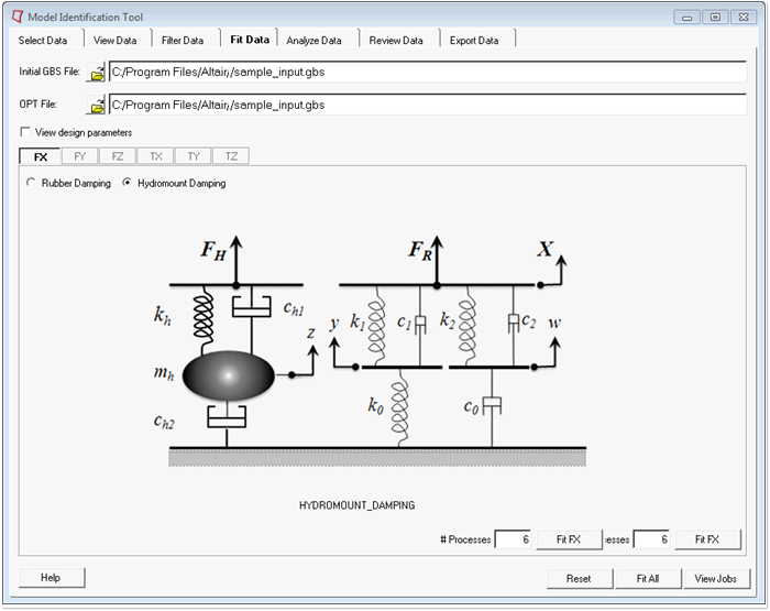
If your project uses a hydromount bushing, then the following page
appears: Figure 2.
Click on Initial GBS File to locate the appropriate
file.
The fitting algorithm requires an initial set of model parameters to initiate
the fitting. These parameters are contained in the Initial
.gbs file. The software searches for a
.gbs file with the same prefix as the Application_Type
field specified in the .spd file. The default model that is
used is based on the Application_Type in the .spd file. If
the software does not find the Initial .gbs file, it uses a
default Initial .gbs file from the installation. The set of
values in the default Initial .gbs file generally works for
most fitting tasks; however, you have the option to provide your own Initial
.gbs file.
Click on OPT File to locate the appropriate file.
To control the fitting, the fitting algorithm requires upper- and lower-bound
values for the model parameters. These values are located in the
.opt file. The software searches for an
.opt file with the same prefix as the Application_Type
field specified in the .spd file. If the software does not
find an .opt file, it uses a default
.opt file from the installation. The set of
optimization parameters in the default .opt file generally
works for most fitting tasks, however, you have the option to provide your own
.opt file.
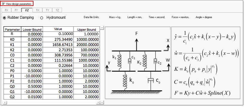
Click View design parameters to view the model
parameters and optimization settings as you see in the following image. You can
modify the parameters as required. Modified values are sent to the fit
tool.
Figure 3.
Click the direction sub tabs FX, FY, FZ, TX, TY, TZ to
select any active direction. A direction is active if the
.spd file contains data for this direction. The
information in the Direction sub tabs comes from the .gbs
and .opt files that were loaded. You can view and modify
the optimization parameters in these tabs.
Click the appropriate bushing model radio button to specify the bushing model
for fitting. If the selected .gbs and
.opt files include the values for this model, the
values are loaded in the table. If the values are not loaded, you have to enter
them. Note that the software automatically selects the correct bushing model for
you so that you do not need to toggle between the models.
Use the Parameter table to change the initial model values imported from the
Initial .gbs files, and the upper and lower bounds for each
of the parameters as specified in the .opt file.
In the # Processes field, enter the number of
sub-processes for the fit operation. If you enter 1 for this option, HyperWorks runs using a single process. For any value greater than
1, HyperWorks uses multiple sub-processes. HyperWorks automatically configures the number of sub-processes to
use.
Click Fit <direction> to run the Fit for a selected
direction. Each Fit is considered as a cycle in the Review tab. You can submit
jobs while a Fit job is running.