The graphics area displays a representation of the geometric layout of the
section.
All sections display the following items:
Item
Description
Local origin of the beamsection
Section Centroid
Shear Center
Element Axis
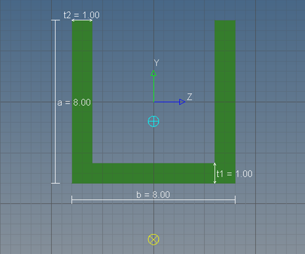
Standard sections display the geometric representation of the section based on the
parameter values, which are also listed on the screen. Figure 1.
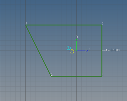
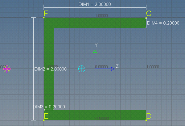
For shell sections each part is drawn with lines connecting the dots that show the
section's vertices. Figure 2.
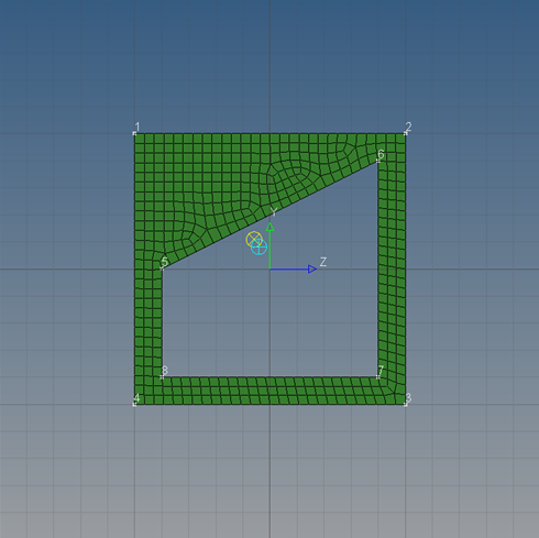
Solid sections can be created and edited using the same tools as a shell section, and
the mesh that is used for the section calculations is displayed. Figure 3.
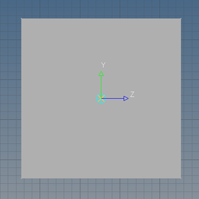
Since generic sections do not inherently have any shape, only a grey box is shown.
The centroid and shear center graphics location will update. Figure 4.
Display Stress Recovery Locations
Toggle the display of stress recovery location points and/or prop IDs that are
already defined within the property solver cards.
Stress recovery points for shells, solids, and generic sections are only supported in
the Nastran, Radioss, and
OptiStruct user profiles.
To access these parameters, click Parameters > Display from the menu bar.
To accept your changes, click Update before you exit the
dialog.
Figure 5.
Modify Grid Parameters in the Graphics Area
You can change the size of the background grid and vertices in the graphics area, as
well as adjust the behavior of your cursor when it is near snap tolerance lines, by
modifying the grid parameters.
Click Parameters > Grid from the menu bar.
Modify the grid parameters.
In the Grid Size field, enter the size of the background grid in the graphics
area.
In the Snap Size field, enter the incremental movement of your cursor over grid
points in the graphics area. If your cursor is not snapping to the nearest grid
points when you move your mouse in the graphics area, increase the snap
size.
In the Point Size field, enter the size of the vertices in the graphics area.
Increasing the point size makes it easier to select an existing grid point when
you are creating a part.
To accept your changes, click Update before exiting the
dialog.