HM-3300: Check and Edit the Mesh
In this tutorial you will check and edit the mesh.
- Identify shell element connectivity problems
- Correct shell element connectivity problems
- Review the model’s shell elements to ensure connectivity problems were corrected
- Remesh the elements along the rib
- Use element quality Cleanup tools
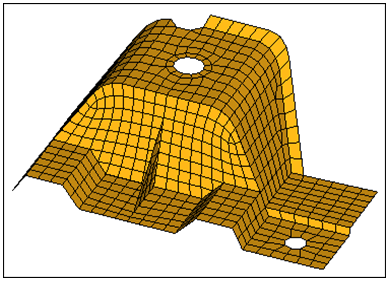
Figure 1.
Open the Model File
In this step you will open and view the model file, cover.hm.
- Start HyperMesh Desktop.
- From the menu bar, click .
- In the Open Model dialog, open the file, cover.hm.
Review Free Edges
In this step you will review the model's free edges to identify shell element connectivity problems.
-
To open the Edges panel, do one of the following:
- From the menu bar, click .
- On the Checks toolbar, click
 (Edges).
 - From the main menu, go to the Tool page and click edges.
- Press Shift + F3.
-
Click find edges.
HyperMesh creates a red 1D element along each shell element edge that is free (one or more of the nodes on the element's edges are not shared by the adjacent elements), and organizes them into a new component named ^edges.Note: If the first character of a component's name is ^, the component and its contents will not be written to the input file when the model is exported.
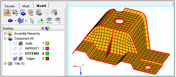
Figure 2. -
In the Model Browser, Component folder, click
 next
to shells to turn off its element display.
next
to shells to turn off its element display.
-
Continue to identify which red, free edges do not belong in the model.
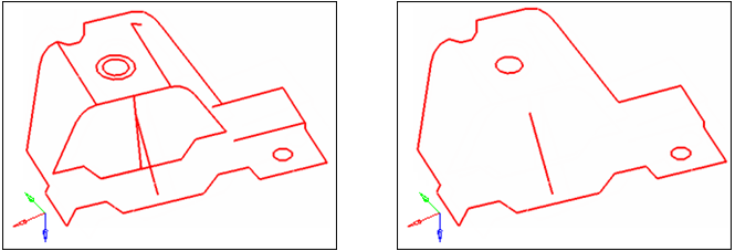
Figure 3.
Correct Connectivity Problems
In this step you will correct the shell element connectivity problems using the Edges panel.
-
In the tolerance= field, increase the value until you
have identified all 96 nodes.
Note: Do not increase the tolerance too much. Although you will identify the 96 nodes, an excessively large tolerance value may collapse elements when the identified nodes are equivalenced.Find the maximum tolerance value that you can safely use without collapsing the elements by pressing F10 to go to the Check Elems panel, 2d subpanel, and clicking length. The status bar reads "The min length is 1.49." This message indicates that you can safely use a tolerance value < 1.49, without causing any elements to collapse when identified nodes are equivalenced. Return to the Edges panel by clicking return.
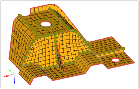
Figure 4.
Review Free Edges
In this step you will review the model's free edges again to confirm that all the shell element connectivity problems have been corrected.
You should still be in the Edges panel.
-
Verify that all free, red edges belong in the model.
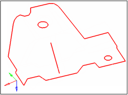
Figure 5.
Display the Element Normals
In this step you will display the element normals and adjust them to point in the same direction.
-
To open the Normals panel, do one of the following:
- From the menu bar, click .
- On the Checks toolbar, click
 (Normals).
 - From the main menu, go to the Tool page then click normals.
- Press Shift + F10.
-
Set the toggle to vector display.
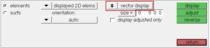
Figure 6. -
Set the top switch to comps.
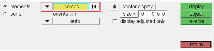
Figure 7. -
Click display.
HyperMesh draws vectors from the element centroids, which indicate the direction of the elemtn normals.Note: The arrows do not all point from the same side of the part. For some analyses, the element normals should point from the same side.
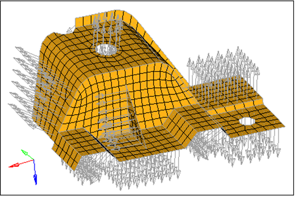
Figure 8. -
Click display.
HyperMesh displays, on each side of the part, the element normals using the colors red and blue.Note: The red side of the elements is the positive normal direction, while the blue side is the negative normal direction.
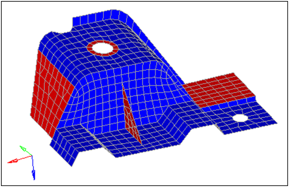
Figure 9. -
In the graphics area, select an element as indicated in the following
image.
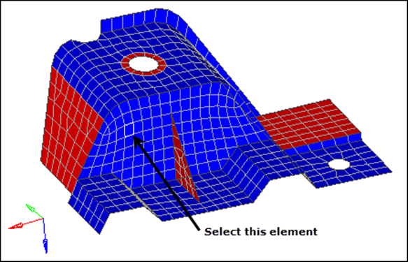
Figure 10. -
Click adjust.
All elements on both sides of the part are the same color, red or blue.Note: The status bar reads: "[X] elements have been adjusted."
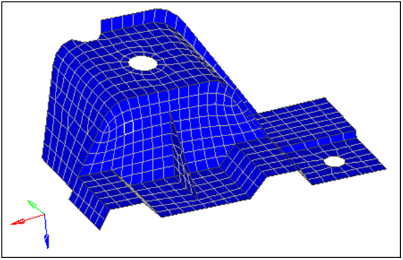
Figure 11.
Review Element Quality
In this step you will review the quality of the elements using the check elems panel.
-
To open the Check Elems panel, do one of the following:
- From the menu bar, click .
- On the Checks toolbar, click
 (Check
Elements).
(Check
Elements). - From the main menu, go to the Tool page then click check elems.
- Press F10.
-
Click jacobian.
HyperMesh highlights the elements that have a jacobian of less than 0.7 and the Status bar displays a message indicating how many elements failed this check.Note: There are several elements on the triangular rib and around the smaller of the two holes that have a jacobian of less than 0.7.
Figure 12. -
In the graphics area, click an element.
A window appears that lists each quality check result for the element.
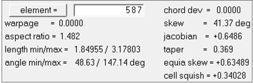
Figure 13. -
Click jacobian.
A legend for jacobian values appears and each element is colored accordingly.Note: Red elements have a jacobian less than the threshold of 0.7.
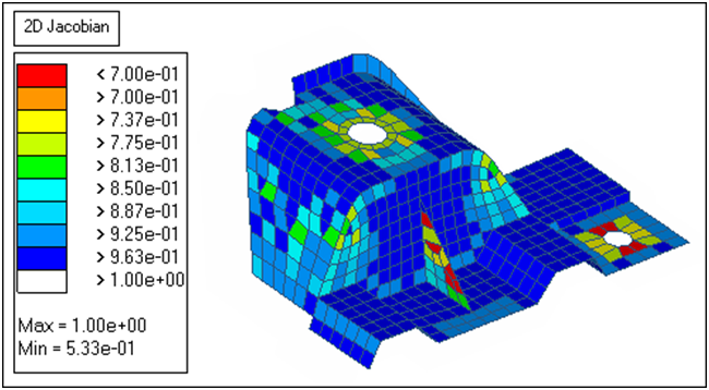
Figure 14. -
Click min angle to determine if any quad elements have
an angle of less than 45.
Note: A couple of the elements on the rib have an angle of less than 45.
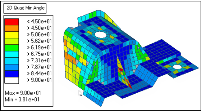
Figure 15. -
Click max angle.
Note: Several elements on the rib have an angle greater than 135.
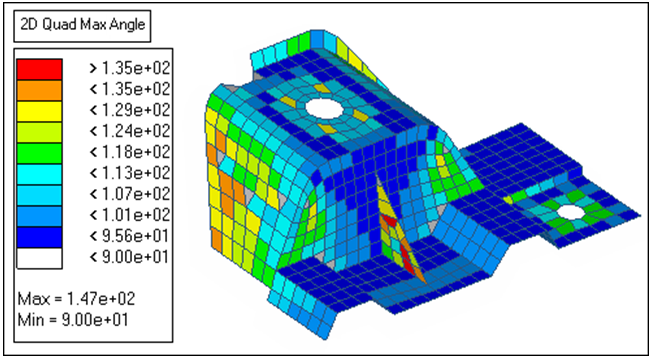
Figure 16.
Remesh Elements Using the AutoMesh Panel
In this step you will remesh the elements on the rib using the AutoMesh panel.
-
Select one element on the plane of elements perpendicular to the rib and in the
same plane as the rib's shortest edge as indicated in the following image.
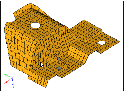
Figure 17. -
Complete your selection of elements by clicking elems >> by
face.
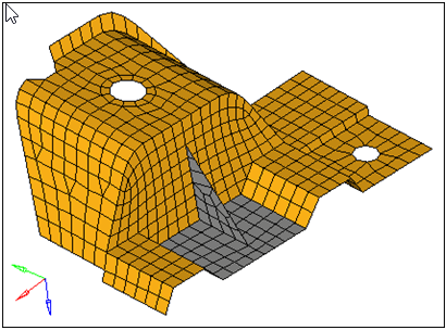
Figure 18. -
Click mesh.
The meshing module opens.
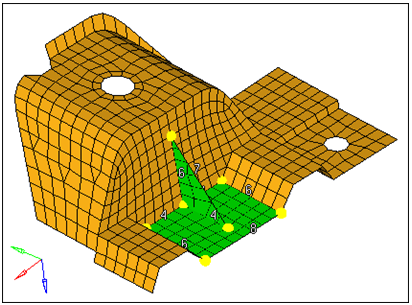
Figure 19. -
In the density subpanel, left-click on the rib's
hypotenuse edge density number to increase it to 9 as indicated in the following
image.
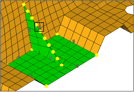
Figure 20. -
Left-click on the rib's shortest edge density number to increase it to 5 as
indicated in the following image.
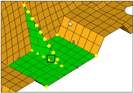
Figure 21. -
Preview the mesh by clicking mesh.
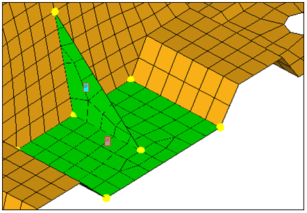
Figure 22. -
Check the jacobian, quads: min
angle, and quads: max angle.
Note: None of the elements failed the minimum and maximum angle checks, and only a couple of the elements have a jacobian of less than 0.7. The smallest jacobian is 0.68, which can still be considered good quality.
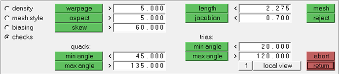
Figure 23. -
Accept the mesh and return to the main menu by clicking
return.
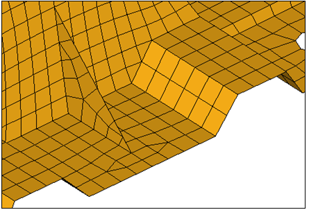
Figure 24.
Adjust the Node Placement
In this step you will use the Smooth panel to adjust the node placement on the rectangular plane of the remeshed elements.
-
Click elems >> by face.
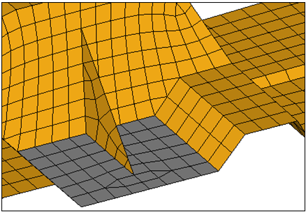
Figure 25. -
Click return.
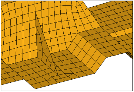
Figure 26.
Remove Tria Elements
In this step you will remove tria elements from another area of the model using the edit element panel, split and combine subpanels.
-
Click the four screen points as indicated in the following image.
HyperMesh draws temporary line segments to connect the points.Note: Right-click to undo the last line segment drawn, or click delete line to start over and reselect points.
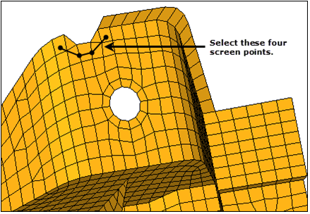
Figure 27. -
Click split.
HyperMesh splits the elements that have a line passing through them.Note: The resulting mesh should look like the mesh in the following image, with two pairs of adjacent tria elements.
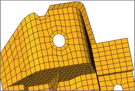
Figure 28. -
Select the two adjacent tria elements as indicated in the following
image.
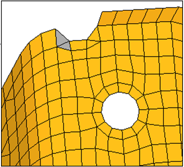
Figure 29. -
Click combine.
HyperMesh combines the two tria elements into one quad element.
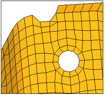
Figure 30. -
Repeat Steps 11.9 and 11.10 to combine the other two tria elements into one
quad element.
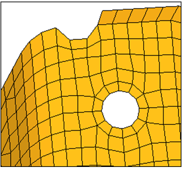
Figure 31.
Modify and Optimize Element Quality
In this step you will modify the washer radius and optimize element quality by using Cleanup tools.
-
Select a node on the washer as indicated in the following image.
The radius field displays a value of 5.98.
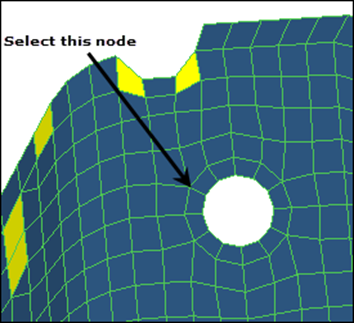
Figure 32. -
Select a node on the washer as indicated in the previous image. The radius
changes to 7.
Note: Because you selected the link washers checkbox, the hole's radius will change accordingly (approx. 4.68). Due to the change in the hole's and washer's dimensions, elements around the washer will be distorted and will fail in quality. You can correct all of the failed elements in the model using the node optimize and element optimize cleanup tools.
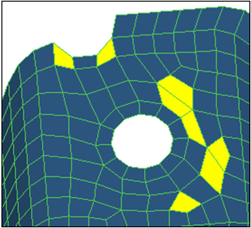
Figure 33. -
Select the red and yellow elements in the model.
When you select an element, HyperMesh adjusts it to have the best quality possible based on the criteria specified in the Quality Index panel.
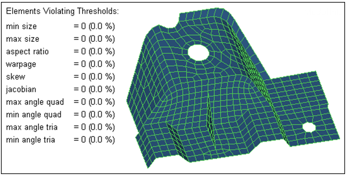
Figure 34. -
Left-click on a tria element and drag it toward the bottom edge of the model
until it is out of the model completely.
HyperMesh highlights the selected tria element in pink.
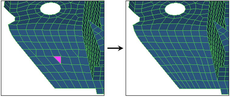
Figure 35.
Add Radial Elements
In this step you will add a ring of radial elements around the smaller of the two holes.
-
Select one of the nodes on the edge of the smaller hole as indicated in the
following image.
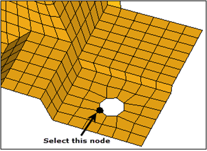
Figure 36. -
Click proceed. HyperMesh
selects nodes around the hole.
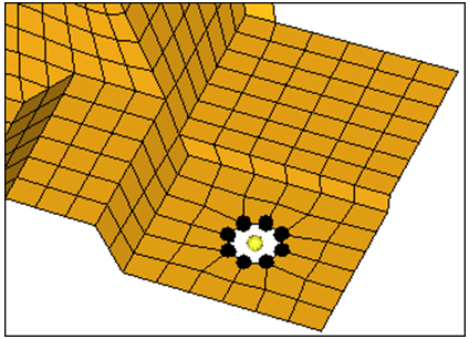
Figure 37. -
In the Density field, type 12.
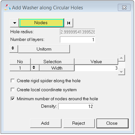
Figure 38. -
Click Add.
HyperMesh creates a washer around the hole.
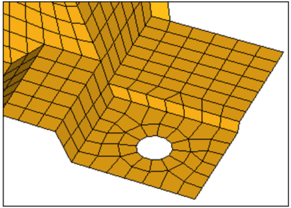
Figure 39.
Imprint Mesh
In this step you will imprint the mesh to different destinations.
-
Go to the imprint subpanel.
Note: Use the imprint subpanel to sync or line up different, overlapping component's meshes in order to facilitate a better connection modeling between the components.
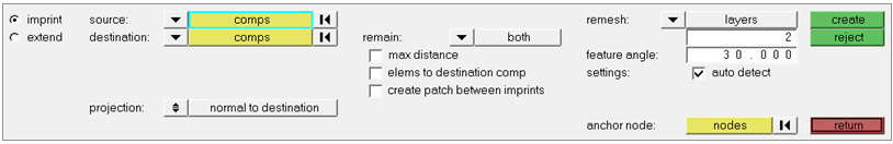
Figure 40. -
From the remain drop-down list, select
destination.
Note: This option takes existing elements/components that can be imprinted into destination elements/components, and changes their direction and destination.
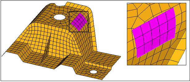
Figure 41. -
Click create.
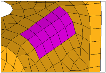
Figure 42. -
Select the elems to destination comp checkbox.
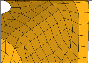
Figure 43. -
Click create.
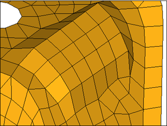
Figure 44.
Extend the Mesh
In this step you will extend the mesh to different destinations.
-
On the EXTEND component, select the source nodes indicated in the following
image.
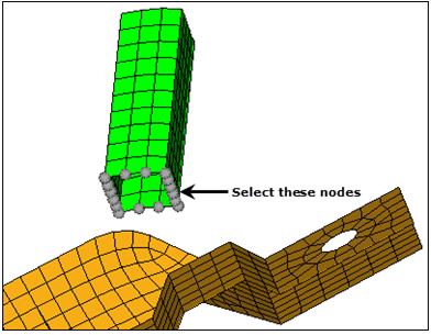
Figure 45. -
Select N1 and N2 to define the
direction, as indicated in the following image.
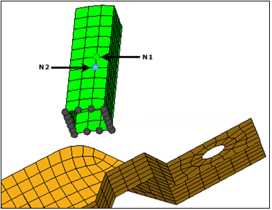
Figure 46. -
Click create.
HyperMesh connects the two parts with one element along the projection because the remesh extension checkbox was cleared.
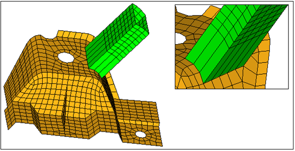
Figure 47. -
Click create.
HyperMesh connects the two parts with remeshed elements along the projection because the remesh extension option was selected.
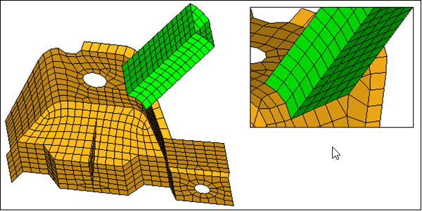
Figure 48.
Save Your Work
In this optional step you will save your work.