Tight Shrink Wrap Mesh

Tight wrap creates a wrapped surface mesh which adheres as closely as possible to the original FE topology representation, automatically detecting and following the surface features of the model.

The accuracy of the output is dictated by the element size: the larger the element size the less detail, the smaller the element size the more detail. This algorithm works differently than the loose wrap in that it projects the nodes of the shrink wrap to the original mesh, hence it is able to more accurately capture features.

Comparison of Tight and Loose Meshing

Notice the differences between tight and loose meshing, especially in the pulleys on the front of the engine and the resulting width of the individual cylinder exhaust pipes.


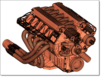
Figure 1. Original Model


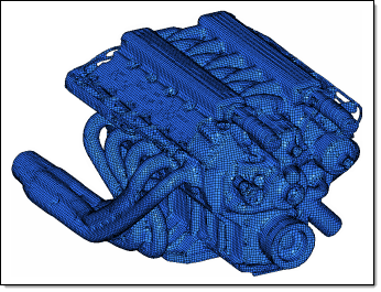
Figure 2. 2mm Tight Wrap


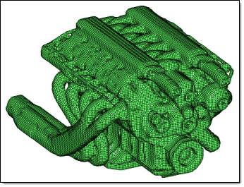
Figure 3. 2mm Loose Wrap

Comparison of Altering the Jacobian Value for Solid Mesh Generation

Within both tight and loose wrap algorithms there is an option to generate solid mesh. This will generate an all-hexa mesh on completion of the shrink wrap. When the generate solid mesh checkbox is active it exposes a minimum jacobian input; this option essentially hexa meshes the part with this element quality criteria defined. It controls the hexa quality which is directly linked to the adherence to the topological features of the original component. The jacobian value must be between 0 and 1. The nearer the value is to 1 the cruder the output will appear (the mesh will be more heavily voxelised). When the value is closer to 0, you allow the shrink wrap solid mesh algorithm to smooth and adhere to more features while maintaining the solid mesh minimum jacobian element quality. By default the minimum jacobian value is 0.3.


Figure 4. Original Model


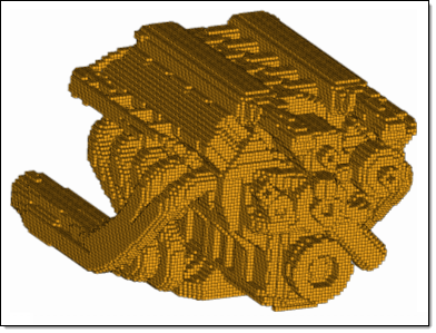
Figure 5. 2mm Solid Mesh, Jacobian=1.0


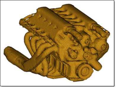
Figure 6. 2mm Solid Mesh, Jacobian=0.3

Shrink Wrapping with Feature Recognition

An additional option can be used to manually define features which will be adhered to during the meshing process. Typically, when using the shrink wrap the mesh attempts to follow features, but has some freedom to break away from original edges of the part. However, when the features are manually selected within the panel the resultant shrink wrap mesh will follow the chosen features. This can be important when defining a face of a component that may be in contact with other parts, or there may just be a feature that needs to be recognized and adhered to and cannot be approximated for whatever reason.


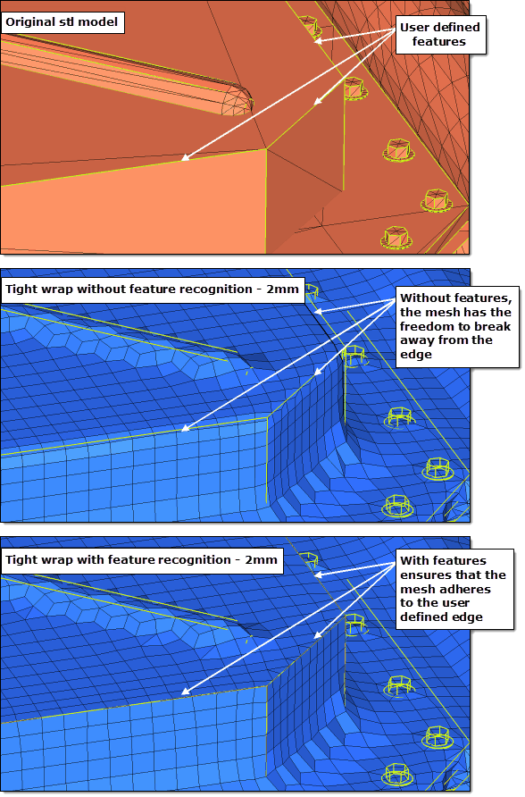
Figure 7. Shrink Wrap with and without Feature Recognition – 2mm

Comparison of using Global and Local Systems for Mesh Orientation

There is also an advanced option to control the mesh orientation. If you have a non-uniform part and you want to re-orientate the mesh so that it follows the features of the original component better then you can use this option. By default the mesh orientation always adheres to the global system, however, you can generate a local coordinate system and override the default behavior.

In the example below, you can see the original mesh, the default shrink wrap mesh using the global system, and the new re-orientated mesh using the local coordinate system.


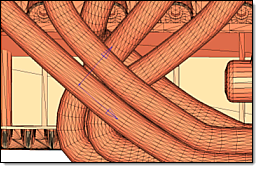
Figure 8. Original .stl Model


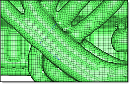
Figure 9. Shrink Wrap Output using Global System. Default shrink wrap mesh using the global system.


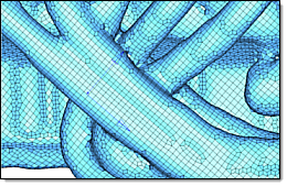
Figure 10. Shrink Wrap Output using Local System. Rows of elements in the reoriented mesh run along the tubes rather than at angles across them.