Edit Plates, Base Surfaces, and Collapsed Lines
Plates, base surfaces, and collapsed lines on the midsurface can be modified using the interim edit tools in the midsurface panel.
The modifications you make to the midsurface using the interim edit tools are not automatically applied. You must delete and re-extract the midsurface in the auto extraction subpanel to apply your changes.
Edit Plates
Plates are a group of surfaces in the model in which the middle surface will be inserted.
Each plate has two sides: blue and green. The middle surface is inserted between the two sides of each plate. When you click show/edit all, surfaces are organized into components that reflect their plate type. To display the plates as per their component color, change the geometry display mode to Mixed on the Visualization toolbar.
When the automatic detection of plates is not correct, click show/edit all to manually edit plates.
Plate information will only be created upon extracting midsurface using the offset+planes+sweeps and offset+planes methods.
Any changes made to the midsurface using the Plate Edit tools will not be visible until you click update within the same panel, or after you extract the midsurface using the offset+planes+sweeps or offset+planes methods.
- From the Geom page, select the midsurface panel.
- Select the interim edit tools.
- Select the edit plates subpanel.
- Click show/edit all.
-
Edit plates.
To edit plates by Do this Creating new plates out of surfaces - Using the single surface selector, select surfaces to create new plates from.
- On the left side of the panel, select a type of plate to create.
- Click new plate.
A new plate is created out of the selected surfaces.
- Continue modifying the midsurface, or click update to re-extract the midsurface.
Creating transition surfaces Transition surface provide more information to the algorithm regarding inserting surface where two regular plates are intersecting. An algorithm calculates how far intersecting plates can be extended based on the transition surface. - Using the single surface selector, select surfaces.
- Click transition surface.
The selected surfaces are used as transition surfaces during midsurface extraction.
- Continue modifying the midsurface, or click update to re-extract the midsurface.
Selecting trim surfaces to ignore during midsurface extraction - Using the single surface selector, select surfaces that you do not want to be considered trim surfaces.
- Click not a trim surface.
The selected surfaces are placed in the component, ^Not a trim surface.
- Continue modifying the midsurface, or click
update to re-extract the
midsurface.
During midsurface extraction, the surfaces in the ^Not a trim surface component will be ignored.
Switching the offset side Each plate has two sides (blue and green) between which the midsurface is inserted. By default, the midsurface is generated by offsetting the green side of the plate. - Using the single surface selector, select surfaces to switch the offset side.
- Click switch sides.
- Continue modifying the midsurface, or click
update to re-extract the
midsurface.
During midsurface extraction, the midsurface will be offset from the opposite side that it was originally offset from. If the midsurface was generated by offsetting the green side of the plate, the midsurface will now be generated by offsetting the new green side which was blue before using switch side.
Assigning trimming surfaces Plate edges act as trimming surfaces for all plate types, and are used to trim inserted midsurfaces. - Using the single surface selector, select surfaces to serve as trimming surfaces.
- Click plate edge.
- Continue modifying the midsurface, or click
update to re-extract the
midsurface.
During midsurface extraction, the midsurface is trimmed using the surfaces you selected.
Merging plates - Using the full plate selector, select plates to merge.
- On the left side of the panel, select a new plate type to create.
- Click merge plates.
All of the selected plates are merged into a single plate.
- Continue modifying the midsurface, or click update to re-extract the midsurface.
Edit Base Surfaces
In certain situations, you may need to extract a midsurface from multiple solids as if they were a single solid.
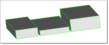
Figure 1.
Normally, this would result in multiple midsurfaces, each one at the middle of the solid it was extracted from, and therefore not aligned with each other.
In the edit base surfaces subpanel you can specify a distance from the base surfaces of multiple solids, that you wish to treat as if they were continuous, to generate separate-but-aligned midsurfaces for during extraction.
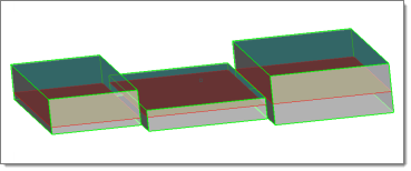
Figure 2.
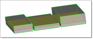
Figure 3.
Edit Collapsed Lines
Enable visualization settings to display point associations on the midsurface after extraction, and manually define lines and line chains to establish the linkage between points that should collapse to the same location.
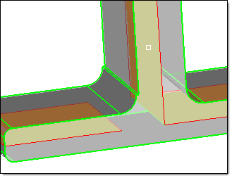
Figure 4.
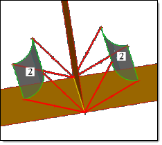
Figure 5. . The curved lines on each fillet are correctly associated with each other.
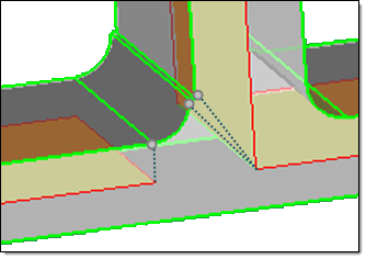
Figure 6. . The step in the fillet caused the extraction tool to associate the two points at the end of the step's edge with each other and collapse (correctly) toward the T-joint of the midsurface, while the remaining points at the other ends of the curved lines were then incorrectly collapsed in a normal direction instead of to the same point.
- From the Geom page, select the midsurface panel.
- Select the interim edit tools.
- Select the edit collapsed lines subpanel.
- Select the allow rerun checkbox.
-
Edit collapsed lines.
To edit collapsed lines by Do this Displaying point associations on the midsurface Pre-requisite: Reject the current midsurface. - Set the switch to prepare for rerun.
- Select the auto extraction subpanel.
- Click extract.
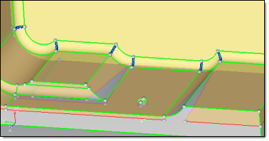
Figure 7.Collapsing lines - Set the switch to do rerun.
- Activate the lines to collapse selector.
- Select each line segment that you wish to collapse to a single point on the midsurface.
- Click collapse. The selected line segments collapse and are highlighted light blue, indicating that they are new collapsed lines.
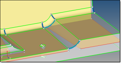
Figure 8. - Select the auto extraction
subpanel.
The collapsed lines that were automatically found during the initial midsurface extraction and the lines that you manually collapsed remain highlighted blue and flagged for collapse.
- Click extract. The original midsurface is deleted and a new midsurface is generated using all of the lines that are flagged for collapse.Note: If allow rerun is disabled or the allow rerun switch is set to no rerun or prepare for rerun, then the lines that you manually collapsed will not be used when a new midsurface is extracted.

Figure 9.
Deleting collapsed lines Pre-requisite: Display point associations on the midsurface. - Set the switch to do rerun.
- Activate the lines to collapse selector.
- Select collapsed lines to delete.
- Click delete.
Trimming surfaces to create additional points and lines - Set the switch to do rerun.
- Activate the trim surfaces with cut line selector.
- Select surfaces to trim.
- Click drag a cut line.
- Click where you wish the line to begin, then click one or more times where you wish the lines to either end or change direction.
- Press Esc.
The line is generated and any selected surfaces it crosses are trimmed.