Setup CAD Models with Metadata

Use metadata generated as part of the CAD import process to setup CAE models.

Rename Components from Metadata Attached to Components

  1. From the menu bar, click Geometry > Metadata to CAE.
    The Metadata to CAE dialog opens.
  2. For Create, select Part Names.
  3. For From, select Components.
  4. For Metadata, select a specific metadata name.
    A list of entities is generated.
  5. In the table, select entities to operate on.
  6. Click Apply.

The new names are taken as the values of the specified metadata attached to each selected component. If there are duplicate names, an incremental name is generated.

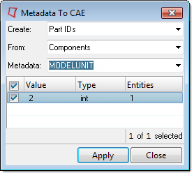
Renumber Components from Metadata Attached to Components

  1. From the menu bar, click Geometry > Metadata to CAE.
    The Metadata to CAE dialog opens.
  2. For Create, select Part IDs.
  3. For From, select Components.
  4. For Metadata, select a specific metadata name.
    A list of entities is generated.
  5. In the table, select entities to operate on.


  6. Click Apply.
The new IDs are taken as the values of the specified metadata attached to each selected component. If there are duplicate IDs, the entities will not be renumbered.

Create Regions from Geometry with Associated Metadata

  1. From the menu bar, click Geometry > Metadata to CAE.
    The Metadata to CAE dialog opens.
  2. For Create, select Regions.
  3. For From, select a type of geometry.
  4. For Metadata, select a specific metadata name.
    A list of entities is generated.
  5. In the table, select entities to create regions from.
  6. Click Apply.

Create Spot Connectors from Points with Associated Metadata

  1. From the menu bar, click Geometry > Metadata to CAE.
    The Metadata to CAE dialog opens.
  2. For Create, select Connectors.
  3. For From, select Points.
  4. For Metadata, select a specific metadata name.
    A list of points is generated.
  5. In the table, select the points to create spot connectors from.
  6. Click Apply.
Spot connectors are created from the selected points using components as links based on proximity. By default, HyperMesh uses two links. You can modify and/or realize the connectors using the Connector Browser or connector panels.

Create Seam Connectors from Lines with Associated Metadata

  1. From the menu bar, click Geometry > Metadata to CAE.
    The Metadata to CAE dialog opens.
  2. For Create, select Connectors.
  3. For From, select Lines.
  4. For Metadata, select a specific metadata name.
    A list of lines is generated.
  5. In the table, select the lines to create seam connectors from.
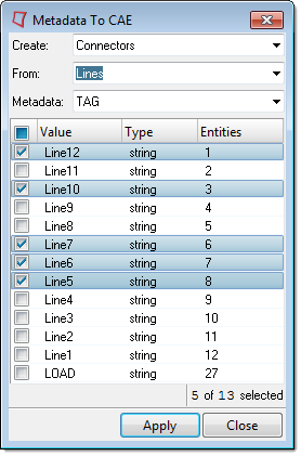

    Figure 1.
  6. Click Apply.
Seam connectors are created from selected lines using components as links based on proximity. By default, HyperMesh uses a spacing of 1.0. You can modify and/or realize the connectors using the Connector Browser or connector panels.

Create Area Connectors from Surfaces with Associated Metadata

  1. From the menu bar, click Geometry > Metadata to CAE.
    The Metadata to CAE dialog opens.
  2. For Create, select Connectors.
  3. For From, select Surfaces.
  4. For Metadata, select a specific metadata name.
    A list of surfaces is generated.
  5. In the table, select the surfaces to create area connectors from.
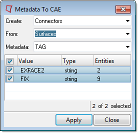

    Figure 2.
  6. Click Apply.

Area connectors are created from selected surfaces using components as links based on proximity. You can modify and/or realize the connectors using the Connector Browser or connector panels. By default, a quad mesh with an element size of 10.0 is used.