Position the Die

Specify the position of the die set for the open and closed states.

The positioning arrow lets you preview the die set between the open and closed states. The position of the die set can be defined automatically or manually.
  1. On the ribbon, hover over an operation that you've added to your analysis.


  2. Click the Edit Position arrow.
    A guide bar opens with three fields.
  3. In the first field, select a tool state for the die set: Open or Closed. To see further modifications for the die in the closed position, see Closed Position.
    The tool position is displayed for the corresponding state. If you adjust the tool position, the last position and the method of the corresponding state is saved.
  4. In the second field, select Auto for the software to position the die set or Manual to position the die set with your mouse.
    Note:
    • The legend in the top left corner of the modeling window indicates the positioning method used for the particular tool in Open or Closed position.
    • Tools are automatically positioned as open and closed when configured if Auto positioning is turned on in Preferences. By default it is on.
    Position Method Description
    Auto
    • The tools available for auto-positioning are highlighted.
    • To remove or change a selection, on the tool, press Ctrl + click, then select a new tool as required.
    • To accept the selections and auto-position the tools, click Position.
    Note: If the tool has been positioned manually in the previous step, it will not appear highlighted unless you click to select it. The bottom die is stationary and cannot be selected for auto-positioning.
    Manual
    • On the model, select a tool to position.
    • Select and drag the manipulator to move the tool to a new position. The manipulator indicates the distance from the selected tool relative to the bottom die.
    • Alternatively, enter the distance in the microdialog.
    Note:
    • To move the manipulator to a desired location on the selected part, press Ctrl and click on the location.
    • The manipulator only moves parts along the draw direction except for the cam die which moves in its own direction.
    • For the top, bottom, or cam pad, the measure tool measures the distance from the attached tool.
    • When you move a top or cam die that includes a top or cam pad, respectively, the die set moves together.
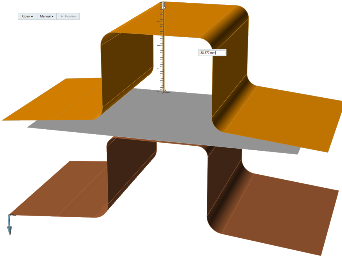
Figure 1. Tool Positioning with Manipulator and Microdialog

Closed Position

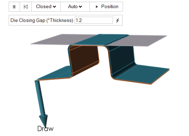
Configure the die position.

Modify the closed position of the die.

  1. On the ribbon, hover over an operation that you've added to your analysis.


  2. Click the Edit Position arrow.
    A guide bar opens with three fields.
  3. In the first field, select a tool state for the die set: Open or Closed. Choose Closed to modify the die in the closed position.
  4. Use the guide bar to configure the die. Click the to modify the Die Closing Gap (*Thickness). If you want to return to Inspire Form's default settings for the tool gap, click on the lightning bolt .