Orient the Stamping Direction
Use the Orient tool to orient the stamping direction for a part.
-
On the Feasibility tab, click Orient.

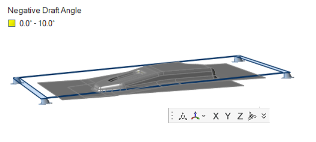
The stamping direction is automatically estimated based on the part's geometry or FE mesh, and the orient plane is displayed.
-
Orient the stamping direction.
- Left-click on a surface or element of FE mesh to use its normal as the stamping direction.
- Use the tools available in the microdialog to
orient the stamping direction.
- Align the stamping direction to an arbitrary direction by clicking
 in the microdialog.
- Align the stamping direction to a user-defined reference system or
Global (
 ).
). - Align the stamping direction to the global X, Y, or Z axis.
- Align the stamping direction to the part (
 ).
). - Define an arbitrary direction by clicking
 and specifying X, Y, and Z direction
cosines.
and specifying X, Y, and Z direction
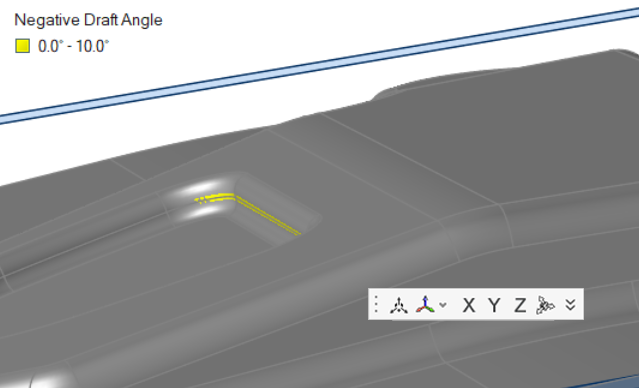
cosines. - Monitor the Negative Draft Angle by using the the legend. Red areas are unfeasible, and yellow areas are passable.
- Align the stamping direction to an arbitrary direction by clicking
 Note: Custom views Draw-Top, Draw-Front, and Draw-Right are created relative to the draw direction so that you can quickly navigate between those views. They are updated automatically whenever you redefine the stamping direction.
Draw-Top The view looking from the top along the draw direction Draw-Front The view from the Front The Front is decided based on the right hand coordinate system with the thumb pointing in the draw direction. The middle finger gives the direction of view from Front to Back.
Draw-Right The view from the Right
The Right is decided based on the right hand coordinate system with the thumb pointing in the draw direction. The index finger gives the direction of view from Right to Left.
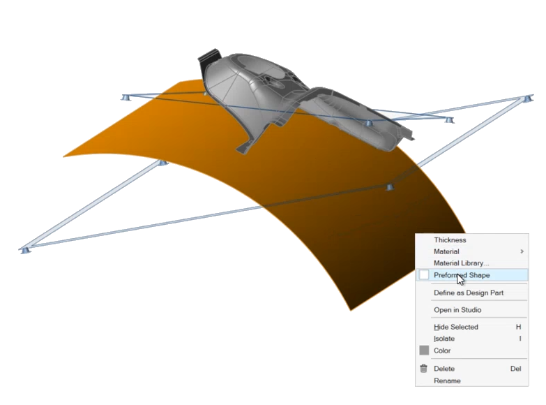
- Optional:
Right-click on geometry or FE mesh with a curvature-continuous surface and
select Preformed Shape to flatten the part to a preformed
shape rather than to a flat blank.
Keyboard Shortcuts & Mouse Controls
| To do this | Press |
|---|---|
| Select part | Left Mouse Click |
| Exit tool | Esc |