Discretisise the model into segments, triangles and tetrahedra (where
applicable).
The solver method affects whether triangles or tetrahedra is created when meshing the
model.
Open the Create mesh dialog using one of the
following workflows:
On the Mesh tab, in the
Meshing group, click the Create mesh icon.
Press Ctrl+M to use the keyboard
shortcut.
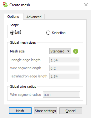
Figure 1. The Create mesh dialog
(Options tab).
Specify the parts to be meshed.
To mesh the full model, under Scope, click
All.
To mesh only the selected part of the model, under
Scope, click Selection.
Select the parts in the model tree or the 3D view before starting the meshing process.
Specify the mesh size.
To create a mesh using automatic mesh sizes, in the Mesh
size field, from the drop-down list
select Coarse, Standard or
Fine.
To create a mesh with a custom mesh size, in the Mesh
size field, from the drop-down list
select Custom. Specify the lengths applicable to the
model.
In the Triangle edge length field, specify
the triangle edge length.
In the Wire segment length field, specify the
wire edge length.
In the Tetrahedron segment length field,
specify the tetrahedron edge length.
In the Wire segment radius field, specify the global
wire radius.
Note: A local mesh refinement takes precedence over global mesh settings.
Click Create to create the mesh and to close the
dialog. A summary indicating the number of mesh elements are logged in the
message window.
Once the mesh settings have been verified on the Create
mesh dialog, you can press Ctrl+Shift+M to perform the mesh without
dialogs or prompts.
 Create mesh icon.