PO Card
The PO card the application of the physical optics approximation is possible.
On the Solve/Run tab, in the Rays group,
click the ![]() Physical optics
icon. From the drop-down list, select the
Physical optics
icon. From the drop-down list, select the ![]() Physical optics (PO) icon.
Physical optics (PO) icon.
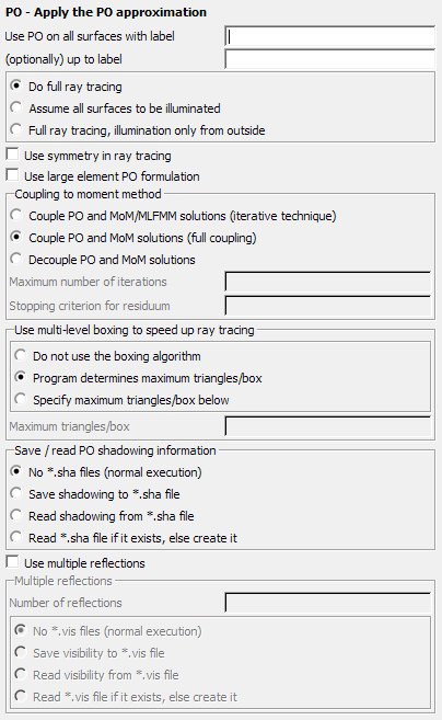
Figure 1. The PO - Apply the PO approximation dialog.
Parameters:
- Use PO on all surfaces with label
- Together with (optionally) up to label are used to specify the label or range of labels of all metallic/dielectric triangles that are treated with the physical optics approximation. If the second field is left blank, only the label specified in the first field is considered. See also LA and CB cards and also general discussion of label ranges.
- Do full ray tracing
- Normal, complete ray tracing is carried out.
- Assume all surfaces to be illuminated
- The ray tracing is switched off to save computational time. The assumption is made that all triangles on which the PO approximation is made are illuminated by the source and the moment method area. The side in relation to the normal vector is automatically determined.
- Full ray tracing, illumination only from outside
- Full ray tracing is done, but metallic triangles can only be lit from the side to which the normal vector is pointing. See note below.
- Use symmetry in ray tracing
- If full ray tracing is done, then symmetry can be used to reduce the computational time required to determine the shading. For electric and magnetic symmetry, this speed up is always used. If geometrical symmetry is used, then this item should be checked to utilise symmetry. It is possible to, for example, define half a plate and create the other half through geometric symmetry. An asymmetric object may then be placed in front of the plate. In this case symmetry should not be used in the ray tracing.
- Use large element PO formulation
- When this item is checked, electrically large triangular patches for PO are allowed (PO).
- Couple PO and MoM/MLFMM solutions (iterative technique)
- A hybrid iterative technique is used to determine the coupling between the MoM or MLFMM region, and the PO region.
- Couple PO and MoM solutions (full coupling)
- When this item is checked, the full coupling between the MoM region and the PO region is taken into account in the solution. The implication is that the currents in the PO region will have an effect on the current distribution in the MoM region.
- Decouple PO and MoM solutions
- When this item is checked, the coupling between the MoM region and the PO region is neglected. The implication is that the currents in the PO region has no effect on the current distribution in the MoM region. This option should lead to a saving in computational time and storage space and is especially useful when the PO region and the MoM is not directly adjacent.
- Maximum number of iterations
- The number of iterations limit for the iterative technique. This parameter is optional.
- Stopping criterion for residuum
- Termination criterion for the normalised residue when using the iterative method. Terminate with convergence when the normalised residue is smaller than this value. This parameter is optional.
- Use multi-level boxing to speed up ray tracing
- The ray tracing required for the physical optics is accelerated by recursively subdividing the problem domain, a so called “multilevel tree”. It must balance memory requirement against speed-up — both increase as the number of levels increases. The number of levels is determined by specifying the number of triangles at the lowest level. The user can specify not to use this algorithm, for the program to determine maximum triangles/box or to specify this number manually. When a number is specified manually, it should be greater than 2 and at least a factor 10 less than the number of triangles in the problem. In general these options should only be set by advanced users.
- Save/read PO shadowing information
- For the PO formulation the information which triangles are illuminated and which are
shadowed from the sources is required. Normally Solver
computes this each time, but there is an option to store this to a file and load again
to save time when the geometry stays constant (say for multiple runs using different
frequencies). The options are:
- No .sha files (normal execution)
- Shadowing information is not stored or read — the default behaviour.
- Save shadowing to a .sha file
- The PO shadowing information is written to a .sha file for later reuse.
- Read shadowing from a .sha file
- The PO shadowing information is read from the .sha file, for example, the ray-tracing part is skipped. For large models this can result in considerable time saving.
- Read .sha file if it exists, else create it
- If a .sha file exists, the PO shadowing information is read from this file. Otherwise the information is calculated and saved in a .sha file for later use.
- Use multiple reflections
- When this item is checked, multiple reflections are considered for the ray tracing. The number of reflections that must be considered is set in the Number of reflections dialog. This parameter determines the number of reflections to be taken into account for triangles with labels in the specified range. (For example, the Number of reflections must be at least 2 to calculate the scattering from a dihedral and at least 3 for a trihedral.) Increasing the number of reflections that must be considered significantly increases computation time, and this should only be done based on physical considerations.
- Visibility information
- The visibility information related to multiple reflections can be saved to reduce the
computation time for future runs. There are four options that can be selected with
respect to saving the multiple reflection visibility information:
- No .vis files (normal execution)
- Visibility information is not used or stored — the default behaviour.
- Save visibility to a *.vis file
- The PO visibility information is stored in a .vis file for later reuse.
- Read visibility from a .vis file
- The PO visibility information is read from the .vis file, for example, the calculation of the visibility information is skipped. For large models this can result in considerable time saving.
- Read .vis file if it exists, else create it
- If a .vis file exists, the PO visibility information is read from this file. Otherwise the information is calculated and saved in a .vis file for later use.
The physical optics (PO) approximation can only be used for certain structures. Structures where the antenna is situated in front of a reflector are well suited. Then PO can be used for the triangles that form the reflector. This results in a large reduction in computational time and memory for electrically large objects.
Note that the ray tracing options and the number of reflections can be specified on a per label basis, by using multiple PO cards. All other parameters can only be specified once. For the global parameters, the values of the last PO card will be used.
- Acceleration of the PO ray tracing with closed bodies (the normal vector must then point outward), since the dot product of the normal and propagation vectors can be used to quickly determine if a triangle is to be used in the ray tracing. In this case the closed model must be constructed with the normals pointing outward.
- In, for example the MoM/PO hybrid method on a closed body, the MoM region (such as an antenna) can be prevented from illuminating the PO region from inside.
A basis function that has been assigned to an edge between two triangles will only be solved with the PO, if the PO approximation has been declared for the labels of both triangles.
The metallic PO region must be perfectly conducting, for example, no losses are allowed. Dielectric coatings (see CO card) and thin dielectric sheets (see SK card) can, however, be treated with the PO approximation.
Large element PO
- The triangular patch must be a large smooth area with no discontinuities of incident field (for example, close to a point source). The surface containing the triangular patch should also not contain any sharp corners.
- The shadowing is done on the triangular patch level, for example, smaller mesh elements are required close to the shadow boundaries.
- For near field calculations (electric or magnetic) or potentials, the maximum triangle mesh size is limited to .
- If only far field calculations are requested, the size of the mesh elements is not limited.
- If near fields calculations are requested, a warning will be given if the mesh size is set equal to or greater than . An error will be given if the mesh size is set equal or greater than .
- As in the case of normal PO, large element PO may not be used in conjunction with UTD.
- The PO solution only or the MoM/PO hybrid solution is supported, but it is then required that the MoM and PO regions are either coupled through the iterative method or decoupled (full coupling is not supported).
- In order to get one wave propagation factor in the PO region, sources (for example, MoM basis functions) must be “close” together.
- Large element PO triangles must be PEC. Note that large element PO may be used in conjunction with normal PO. Connections between normal PO and large element PO are allowed.
- No edge/wedge correction terms are allowed for labels where large element PO is used.
- No extraction of singular terms for near field computations, for example, near fields are inaccurate closer than .. from surfaces.
- The export of surface currents and visualisation in POSTFEKO are not supported for large element PO regions.
- Multiple reflections are not allowed in the model if a large element PO region is present. When multiple reflections are present, RL-GO and faceted UTD should be the preferred method.
- Periodic boundary conditions are not allowed to be used in conjunction with large element PO.
- A BO ground for example a PEC plate or a real ground.
- Symmetry may be used (also for ray-tracing).
- Shadowing effects but not when located inside of individual large triangles.
- Parallel processing (for example, parallel ray tracing, parallel field computations and others.)
- Near field (E, H and potentials) computations as well as far field computations including RCS are allowed.
- All impressed sources my be used in conjunction with the large element PO.