Create the model in CADFEKO.
Define any ports and sources required for the model. Specify the operating frequency or
frequency range for the model.
-
Set the model unit to millimeters.
-
Define the following variables.
- fmin = 1.3e9 (The lowest
simulation frequency.)
- fmax = 1.5e9 (The highest
simulation frequency.)
- h = 70 (The height of the
dipole.)
- wireRadius = 0.1 (The radius
of the dipole segments.)
-
Create the dipole.
-
Create a line.
- Start point: (0, 0,
-h/2)
- End point: (0, 0,
h/2)
- Label: dipole
-
Add a wire port (vertex) to the middle of the line.
-
Label the port Port1.
-
Set a continuous frequency range from fmin to
fmax.
-
Create a general network using a SPICE circuit.
-
Rename the label to MatchingNetwork.
Note: The network label must correspond to the internal network name
used in Match_circuit.cir.
Matching circuit
.SUBCKT MatchingNetwork n1 n2
c1 n1 0 2.43pF
l1 n1 n2 41.2nH
.ENDS NWN1
.end
-
Create a voltage source.
-
For Port select
MatchingNetwork.Port1
-
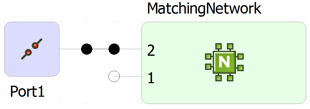
In the schematic view, connect Port1 (the dipole) to Port2 of the
network.
Figure 1. Schematic view of the matching network and port of the
dipole.