Run Analysis
Define and run a filling analysis, solidification analysis, or both.
You need to define a cast part and add gates and other optional components before running an analysis.
-
Click Run Analysis on the Analyze icon.

-
Define the parameters.
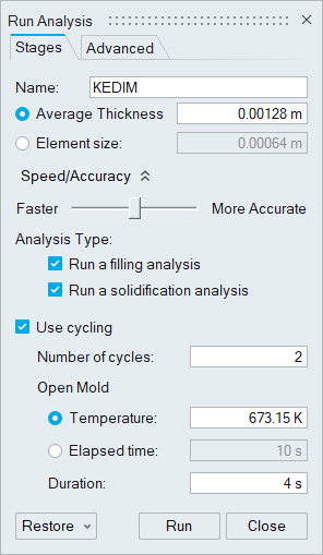
Option Description Name Type the name of the run. (By default, the name of the model is used.) Average Thickness Select this to enter the average thickness of the part. Element Size is updated with changes to this value. Element Size Select this to enter the element size of the mesh, which dictates the quality of your results. In general, the smaller the element size, the more accurate the result, but the slower the analysis will run. Speed/Accuracy If you select Average Thickness, you can use this slider to adjust the speed and accuracy of the analysis. Faster increases the element size, while slower increases the accuracy. Element Size reflects this change. Run a filling analysis When running a solidification analysis only, the starting temperature will be the same throughout the entire part. When running both filling and solidification analyses, the temperature distribution at the end of the filling analysis will be used as the starting point for the solidification analysis.
Run a solidification analysis Use cycling Check to include preliminary cycling to prepare for the casting run. Number of cycles Enter the number of cycles to run. Temperature Enter the temperature at which to open the mold. Elapsed time Enter the amount of time elapsed before opening the mold. Duration Enter the amount of time that the mold is open before beginning the next cycle. Run without mold Click the Advanced tab to create a virtual mold and enter values for temperature and HTC, allowing the analysis to run more quickly. This option is useful if you don’t need to analyze the mold temperature. Component Mesh Factors Click the Advanced tab to adjust the mesh size for each component that you have defined. Enter a factor to multiply the Element Size by. The available range for each of the components except the mold is 0.2-3.
The range of the mold will change depending on the Element Size (or Average Thickness) you have selected. The smaller the element size is, the bigger the factor and range.
Liquid grade factor Enter a value to edit the transition (how the mesh grows) between two different bodies (part, runner, overflow, riser. etc.) that are in a liquid state during casting. Solid grade factor Enter a value to edit the transition (how the mesh grows) between two different bodies (chiller, mold, sleeves, etc.) that are in a solid state during casting. Auto refinement Select to enter values for - Minimum thickness: If the distance between surfaces are within the minimum thickness, the mesh will be refined on these surfaces.
- Minimum size: The mesh refinement will not create elements with edges smaller than the specified minimum size.
- Minimum number of layers: The mesh refinement creates layers of elements in thin sections inside a body. The number of layers can be more than minimum number of layers defined here provided that the edge length is greater than the minimum size.
Use advanced meshing with SimLab If this option is selected, SimLab will be launched when you run an analysis so that you can perform advanced meshing. Note: To restore the default options, click Restore. -
Click Run.
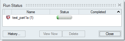
The run status is displayed.