Signal Processing
Produce a heat map and/or IQ Data with the same algorithms that FMCW signal processing equipment would use, to visualize the effects of limitations in such algorithms and/or optimize the parameters in such algorithms.
FMCW Signal Processing
To obtain such a heat map and/or IQ Data, do the following:
- In the results tree, select Power (MS) or Power. These are the power received by the receiver antenna and the power received by a hypothetical isotropic antenna, respectively.
- Click .
- Click on the radar result pixel.
- On the FMCW Radar Postprocessing dialog, specify the parameters.
You can specify the radar parameters using two modes, either with Set Radar Parameters or Design Radar Parameters.
Set Radar Parameters
-
- Chirp duration
- The sawtooth chirp sweep period in μs. It has an impact on the maximum measurable velocity and on the velocity resolution1 of the radar.
-
- Sweep Bandwidth
- The difference between starting and final frequency of a chirp. It has an impact on the maximum measurable range and on the range resolution2 of the radar.
-
- Number of Chirps
- The number of chirps in one frame. It has an impact on the velocity resolution.
-
- Frequency Bins
- The number of FFT samples in one chirp. It has an impact on the maximum detectable range.
Design Radar Parameters
You can specify performance quantities like the desired range, range resolution, maximum velocity, and velocity resolution. It will calculate/design the radar parameters (for example, chirp duration, sweep bandwidth, number of chirps, and FFT samples) that can satisfy the required performance quantities.
You can specify the desired output and optionally the type of windowing function. Windowing functions are applied in the time domain to suppress the side lobes in the frequency domain. It is also used to detect low signals that could be hidden beneath the side lobe of another target.
If a heat map is chosen, it will be plotted. If IQ Data is selected, it is written to disk in ASCII format for external signal processing.
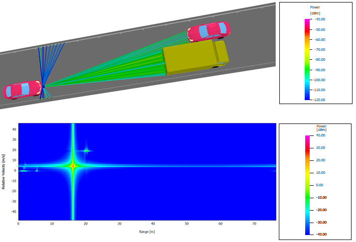
Figure 1. A snapshot in a time-variant simulation and an example of the heat map produced by FMCW processing. This heat map shows not only the range and relative velocities, but also the artifacts produced by the signal-processing algorithm with user-defined parameters.