Modulation and Coding (TDMA)
Modulation and Coding Schemes (MCS) for TDMA Systems
A list with all currently defined MCS can be found at and click the Air Interface tab. Further transmission modes can be defined, existing ones can be adapted during the planning process. The defined transmission modes can be sorted considering various criteria. The order of the MCS does not influence the simulations but the sequential arrangement in the Tree View and on the dialogs.
Figure 1. The Transmission Modes (MCS) dialog.
The following dialog shows the parameters which define a transmission mode of a TDMA system in ProMan. The settings can be specified for the downlink (BS to MS) and the uplink (MS to BS) direction separately.
Figure 2. The Transmission Mode dialog.
- Name
- Arbitrary name for transmission mode.
- Direction to be analyzed
- Downlink and uplink directions can be analyzed individually for each transmission mode. Accordingly it is possible to analyze transmission modes for Only Downlink or for Only Uplink without impact of the other direction.
- Consider mode during simulation
- If this option is enabled, the transmission mode will be considered during network planning simulation. Transmission modes which are specified to be not considered during simulation are display with red text color in the Transmission Modes (MCS) list.
- Position of mode in simulation sequence
- The position (priority) of the transmission modes affects the throughout results
as the transmission modes are analyzed according to their position value.
Typically the networks are configured to maximize the throughput. For this purpose
the transmission mode with the first position should be analyzed first. If there
are some radio resources remaining then the transmission mode with the second
position will be analyzed for checking if the throughput can be further increased
and so on. So to maximize the throughput, the transmission modes should be
assigned reasonable values for the position. Without this sorting it might happen
that transmission modes with low data rates use the available radio resources and
thus the maximum throughput is not exploited.Note: It is not possible to have multiple transmission modes with the same position in simulation sequence. The individual positions of the transmission modes do not have to be consistent (gaps are possible).
- Data Transmission Parameters (for downlink and uplink)
-
- Modulation
- Modulation scheme used for data transmission.
- Code rate
- The code rate states the portion of the total amount of information that is useful (that is non redundant). If the code rate is k/n, k bits out of n totally generated bits are useful information, whereas (n-k) bits are redundant. The redundant bits are used for error detection and correction.
- Nr of Timeslots
- Number of time slots, which can be used for this transmission mode.
- Overhead ratio
- Ratio between gross and net data rate.
- Data rate (read only)
- Net data rate, which is automatically computed according to the parameters specified above.
- Radio Parameters (for downlink and uplink)
-
- Minimum required SNIR
- Minimum signal-to-noise-and-interference-ratio, which is required to use this transmission mode. Receiver locations, where the predicted SNIR is above this threshold will be assigned to this transmission mode and the maximum available data rate for the corresponding Rx locations will be set to the value specified for this MCS.
- Minimum required Signal Level (optional)
- Optional threshold of signal level, which is required to use this
transmission mode.Note: The specified minimum signal level for the uplink direction refers to the input of the base station receiver and not to the power received directly at the antenna. In case a cable loss is defined, the received power at the antenna is additionally reduced by the cable loss before it is compared to the specified minimum required signal level.
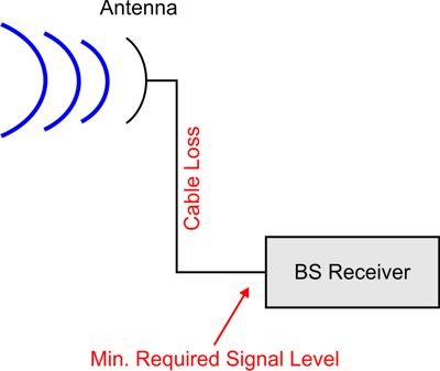
Figure 3. Antenna and Base Station Receiver scenario. - Tx power backoff
- Power headroom which can be specified related to maximum available
transmit power of the base station (for downlink direction) or the mobile
station (for uplink direction), respectively. This headroom can be used
to reduce available transmission power and therefore crosstalk
probability for high modulation and coding schemes.Note: This back off value influences only the transmit power used for data transmission. The power assigned for pilot signals is not influenced.