Altair SimSolid 2021 Release Notes
Highlights
Highlights of this release include the following:
- Orthotropic material
- Fatigue Analysis using uniaxial and multiaxial method for E-N (strain-life) approach
- Fatigue Analysis using uniaxial method for S-N (stress-life) approach
- Stress linearization
- Execute SimSolid functions using a JavaScript file
- Parallel installation of multiple versions
- Enhanced material database supports fatigue material curves and orthotropic material properties
New Features
- Orthotropic material
- Orthotropic materials are now supported. The material properties for these
materials differ along mutually orthogonal axes. You can add them to the
material database by choosing the orthotropic
material type.
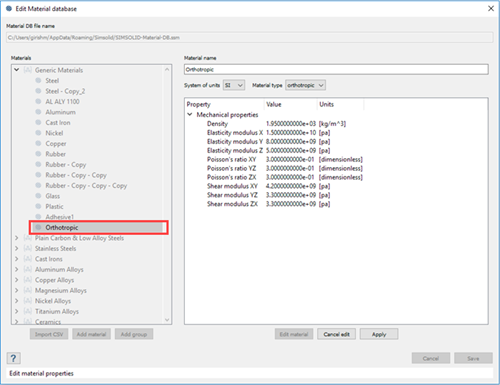
Figure 1. - You can define orthotropic material in the context menu for a selected part
in the Assembly workbench.
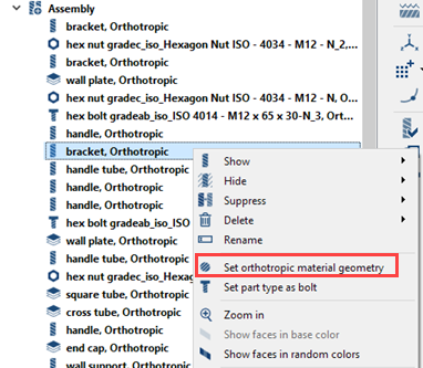
Figure 2. - Fatigue Analysis using E-N (strain-life) approach
- Uniaxial and multiaxial fatigue methods using the E-N (strain-life) approach
are supported. Time-series histories and sequential load cases are
supported. Time series histories can be imported from
.rsp, .rpc, or
.csv files.
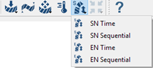
Figure 3. - Fatigue Analysis using uniaxial method for S-N (stress-life) approach
- You can now solve uniaxial fatigue analysis using the S-N (stress-life) approach. Various stress combinations including maximum principal stress, absolute max principal, signed von Mises, signed max shear and critical plane are supported.
- Stress linearization
- Elastic stress field can now be decomposed through thickness into equivalent membrane, bending and peak stresses. This is supported for linear static analysis. Failure criteria can also be defined for linearized local stresses.
- You can access the linearized stress function through the Pick info tab on
the Analysis Workbench. You can draw stress
linearization segments normal to surface or define them by picking end
points for the segment.
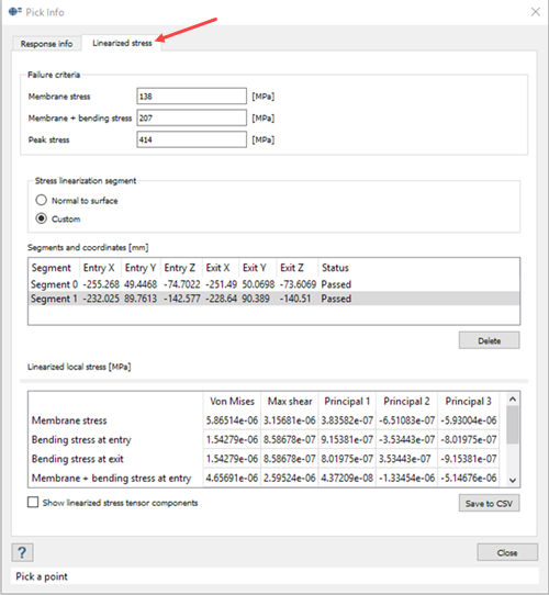
Figure 4. - Execute SimSolid functions using a JavaScript file
- You can now run SimSolid in batch mode using a JavaScript file. This capability is only available for the full version of SimSolid. With this mode, you can run various operations by executing a JavaScript file through command line arguments. The JavaScript file can also be parameterized and executed using command line arguments. Modal analysis with regular connections is currently supported. Applying boundary conditions is not currently supported.
- Sheet repair
- You can repair sheets with self-intersections to remove the
self-intersections. You can also repair sheets with regions of different
than nominal thickness to have uniform nominal thickness through the entire
part. SimSolid indicates sheets with
self-intersections in red, and sheets with different than nominal thickness
in orange. The process to repair sheets is iterative, you may want to repair
sheets and re-run to confirm all defects are repaired correctly. Re-run
until you achieve the desired effects.
You can also review highlighted parts in the Project Tree.
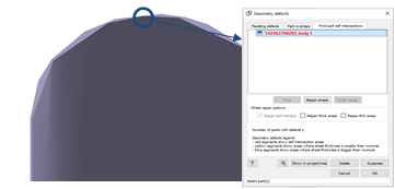
Figure 5. - Parallel installation of SimSolid
- With parallel installation, you can install more than one version of SimSolid on a single system.
Enhancements
- Material database
- The material database now supports orthotropic material properties and fatigue material curves. Under fatigue properties, both stress-life and strain-life curves are supported. You can estimate fatigue properties from UTS, input them with the slope method, or import them from a .csv file.
- SimSolid's new smart material database only
invalidates the results of analyses when you change material properties that
affect that simulation. For example, if you add or edit fatigue properties,
all fatigue analyses using that material are invalid but structural analyses
remain valid.
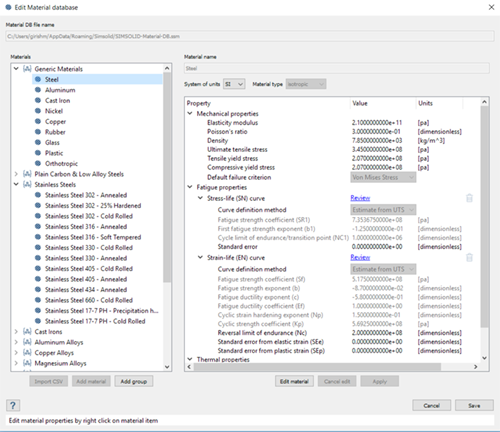
Figure 6. - Bearing load
- You can now apply bearing loads to all surfaces of revolution including cylinders, cones, toruses and so on. You can apply bearing loads as forces in radial and axial directions, and as torque to the selected faces. Copying and editing existing bearing loads is now supported.
- Coordinate system
- You can use the coordinate system dialog to create a local coordinate system to which boundary conditions can be later applied. Defining a system axis by rotating the system about a local axis is now supported.
- Linear dynamics
-
- Absolute acceleration output - Absolute acceleration output is supported for transient analysis with base excitation of type acceleration. Absolute acceleration output is the total acceleration that includes specified enforced motion.
- Peak response evaluation - For transient, frequency response and random response analysis, you can calculate all result peaks over the range of frequencies or time steps during solving. This helps plot the contour instantaneously. Turn on this function by selecting the Evaluate all peak responses during solving check box in the dynamics response setup dialog.
- Basic product package
- SimSolid Basic now supports all project files containing just Structural linear and/or Modal, irrespective of the version or product package used to generate the project file.
- Updated CAD import formats
- The list of supported CAD formats is updated as shown:
File Format Supported Versions CATIA V4 (.model, .dlv, .exp) All 4.xx CATIA V5 (.CATPart, .CADProduct) R10 to R30 CATIA V6 (.3Dxml) 2011to 2013x 3D Experience (.3Dxml) 2014 to 2020x Inventor (.ipt, .iam) All to 2021 JT (.jt) 7.0 to 10.5 Pro/Engineer (.prt, .asm) 13 to Creo 7 ACIS (.sat) All to R27 SOLIDWORKS (.sldpart, .sldasm) 99 to 2020 STEP (.stp) 203/214/242 STL (.stl) Ascii/Binary Parasolid (.x_t) All to 32 NX/Unigraphics (.prt) 11 to NX CR 1953 - Other
-
- Decimal using non-English keyboards works as expected in all the dialogs.
- Brake rotors are now identified in SimSolid. Right-click on the part and choose Pick info. Parts recognized as rotors have special geometric adaption.
- Total strain energy is output for static analysis. You can review from structural analysis . Plot strain energy per part with Results plot; query strain energy using Pick info.
- Review adhesive mass by right-clicking on the adhesive connection and selecting Pick info. Mass and volume of adhesive is now included in Assembly info.
- Geometric nonlinear analysis now supports animation of the results.
- The mode shapes outputs from modal analysis to a UNV file are now mass normalized.
- Mode shapes can be exported in terms of deformed geometry to
.ssg/.stl files. To do
this, right-click on the modal analysis results branch and select
Export in the context menu. You must plot results to activate
this function. To export a deformed shape for modal analysis, you
should enter a maximum deformation as the displacements are
normalized in modal analysis.
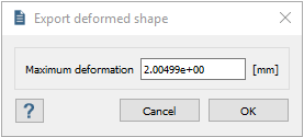
Figure 7. - 3D solid seam welds created in SimSolid can be exported as .ssg/.stl file. Right-click on a specific weld connection to export it, or right-click on the seam weld folder to export all welds.
- Running all analysis in a project or design study will suppress all the warnings to run all the analysis sequentially. A summary of all warnings/errors are displayed after the run.
- Recognition of sheets and features such as torus faces are improved.
- You can now query multiple parts by ID/names by right-clicking on .
- Additional hardware information is displayed under Hardware settings.
- Reaction forces are available at connections, spot welds and bolts for structural superposition.
Known Behavior
- The modal frequencies can change slightly depending on the number of frequencies extracted. In case of many extracted modes, SimSolid's adaptation to high frequency modes can slightly impact lower modes.
Resolved Issues
- Issues related to soft bushings.
- Issues related to inertia relief and pressure load.
- Numerical instabilities running analysis with high adaption.
- In dynamic analysis, the default upper limit of frequency span is set to 60% of the largest natural frequency. You can edit this.
- Issues related to bolt/nut resultant forces with bolt/nut tightening for linear static analysis.
- You can now edit all contact conditions. You can over-write incorrect assignment of contact conditions along bolts/nuts. It is recommended to have sliding contact at the bolt shank and required to have bonded contact at the bolt thread for pretension loads.
- NA (not applicable) is now displayed in the ‘found gap or penetration’ column under ‘review regular connection’ dialog for connections at bolt shank and nut threads. SimSolid creates special connections at above mentioned locations and assumes no gap/penetration irrespective of the physical gap/penetration.
- Part overlap checks on import have been improved.
- Existing product crashes and display issues.
- Issues related to bolt and nut recognition.
- Issues related to seam weld recognition and realization.
- Issues related to creation of regular connections, including split connections by faces.
- Issues related to bringing up the part context menu with deformed shape enabled.
- Onshape mouse setting with regards to zoom in and out.
- Minimum diameter for imported spots is set to 0.1 mm irrespective of the geometry units.
- Issues related to the position of the parts during geometry import.