Altair SimSolid 2021.1 Release Notes
Highlights
Highlights of this release include:
- Incremental loading for nonlinear geometric analysis
- Spot weld fatigue analysis
- Orthotropic materials support thermal expansion coefficients
- Small/large prescribed rotations
- Flexible remote mass
- Improved solution performance for protruded parts
- 3DConnexion space mouse support
New Features
- Incremental loading for nonlinear geometric analysis
- Geometric nonlinear analysis can now be run by incrementally applying
the load and the number of load increments is user-defined. Result plots
for all the result types and reaction forces are available across all
the load increments.
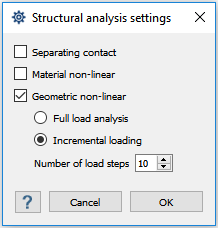
Figure 1. - Spot weld fatigue analysis
- Spot weld fatigue is now supported for stress-life method. It is
supported for both sequential and time-history based solution.
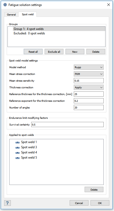
Figure 2. - Orthotropic material supports thermal expansion coefficients
- Thermal expansion coefficients along three axes can be defined for orthotropic material. Thermal distortion studies can now be performed using SimSolid.
- Small/large prescribed rotations
- Prescribed rotations can be defined using remote load/displacement for all structural and multi-loadcase analysis. The remote load supports enforcing both translations and rotations at a remote point location. The translations can be applied in mm, and the rotations in degrees. They can be applied in a global or local coordinate system.
- Flexible remote mass
- A new flexible remote mass type is now supported under . This type of remote mass is connected to the faces/spots without completely rigidizing them, but borrowing stiffness from connected parts. It is still recommended to create remote masses locally in the structure.
- Improved performance for protruded parts
- Parts that have similar cross-section across their length are now recognized as protruded parts. They can be reviewed from the Assembly workbench using . The solution performance for such parts have been improved both in terms of run-time and memory footprint. Running analysis on protruded parts is up to 6 times faster with memory requirement reduced by up to 90%. The performance gains are higher with larger and more complex assemblies.
- 3DConnexion space mouse
- SimSolid now supports 3DConnexion’s space mouse and 3DConnexion 3Dxware, version 10.6.5 or newer is required. Space mouse provides interactive motion control of 3D geometry in up to six degrees of freedom, It works in conjunction with a standard serial mouse. Space mouse is currently not supported on virtual machines.
- SimSolid Advanced product package
- A new product called "SimSolid Advanced" is now offered in AU Mechanical Engineer, AU Mechatronics Engineer and AU Enterprise Suite. SimSolid Advanced draws 50 AU’s and provides access to incremental loading for geometric nonlinear analysis, fatigue analysis and batch mode.
Enhancements
- Displacement magnitude along force direction
- Displacement magnitude across faces with force load along the direction of force is available for quick stiffness assessment. This functionality is available via for structural and multi-loadcase analysis. It is supported for force and remote loads only.
- Rigid option for bushing stiffness
- Bushings can now be created with a ‘rigid’ option in the stiffness. A rigid option will add very high relative stiffness simulating a rigid connection. A ‘0’ stiffness can also be now defined proving complete freedom for the connection along the defined direction.
- Signed von Mises stress
- A new result type called "signed von Mises stress" is now available. The sign of the signed von Mises is determined by the sign of that principle which has the highest absolute value.
- Enhanced material database
- Enhanced material database now supports review of SN/EN curves.
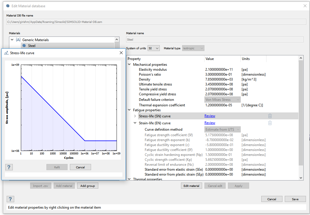
Figure 3. - Enhanced coordinate system
- Coordinate system dialog can be used to create a local coordinate system to which boundary conditions can be later applied. It now supports defining a system axis by translating and rotating the system about a local axis. There is also a new user selection mode to define origin at the COG of selected faces. A custom coordinate system is also supported that can be created from the load dialog directly.
- Updated CAD import formats
- The list of supported CAD formats has been updated as:
File Format Supported Versions CATIA V4 (.model, .dlv, .exp) All 4 xx CATIA V5 (.CATPart, .CADProduct) R10 to R31 CATIA V6 (.3Dxml) 2011 to 2013x 3D Experience (.3Dxml) 2014 to 2020x Inventor (.ipt, .iam) All to 2021 JT (.jt) 7.0 to 10.5 Pro/Engineer (.prt, .asm) 13.0 to Creo 8 ACIS (.sat) All to R27 SOLIDWORKS (.sldpart, .sldasm) 99 to 2021 STEP (.stp) 203/214/242 STL (.stl) ASCII/Binary Parasolid (.x_t) All to 32 NX/Unigraphics (.prt) 11 to NX CR 1969 - Other enhancements
-
- Minimum and maximum
results across selected face(s) are now available.
now displays face min/max and average values of the result type for structural and multi-loadcase analysis. It also lists the coordinates of face min/max.
- Bolts with conical heads are now recognized during import. This recognition provides you the ability to apply pretension loads.
- Linearized stresses can be queried at datum point sets.
- Reaction and spot weld forces are now available for multi-loadcase.
- Reactions at bushings can be output in local bushing coordinate system.
- Orthotropic material properties are validated during input.
- Virtual joints can now be used with large displacement geometric nonlinear analysis.
- Solution errors caused by local geometric irregularities highlight the regions with issue.
- Improved target axial force achievement with bolt/nut tightening by improving the solution adaptation around the bolts.
- Improved virtual connectors representation from point-cloud based to face-based to increase the connectors fidelity.
- Increased the allowable limit for maximum number of modes to 2000.
- The rotation center for CATIA mouse setting can be changed by a click of the middle mouse button.
- Part display status is retained when following tasks are used: Review part connections, review part contact conditions, zoom for parts/connections, selecting regular connections and virtual connectors in the project tree.
- Universal joints can be defined by connecting more than two faces.
- Improved error messages with importing materials to the database.
- Minimum and maximum
results across selected face(s) are now available.
Resolved Issues
- Issues related to connections on nuts and cylindrical faces.
- Issues related to contact conditions at bolts.
- Issues related to geometrical instabilities.
- Geometry recognition issues during import.
- Several crashes with the product.
- Issues updating bolt pretension.
- Disabled the ability to create multiple gravity loads.
- Disabled ability to cancel on save as it leads to corruption of the project.
- Issues related to inconsistent results with copy of force/displacement.
- Restricted connections gap/penetration tolerance to zero or positive numbers.
- Restricted fatigue strength reduction factor to be greater than or equal 1.
- Issues with weak bushings.
- Issues related to adhesives in thermal analysis.
- Issues related to reactions at adhesives in non-linear geometric analysis.
- Issues related to stresses in dynamic analysis with distributed mass.
- Issues related to conflict between elasticity modulus and stress-strain curve for materials in the project.
- Issues related to seam weld generation from solids and lines.
- Issues related to importing materials via SimSolid plugin within SolidWorks.
- Removed the ‘Hide CAD Welds’ option from the Connections context menu.
- Issues related to reactions at virtual connectors.
- Issues related to mapping imported remote loads.
- Issues related to frequency response analysis with translational inertia.
- Issues related to renaming connections that include material information.
- Issues related to adding parts to the ‘Edit connections’ dialog from the Project Tree.